Overview
The part cooling capability of an afterburner isn’t great. It is however simple to swap from an afterburner to a stealthburner without swapping the extruder.
Please note there are no free pins to run the neopixels.
Printed Parts Required
Here is a list of the printed parts required.
- Stealthburner main body
- Stealthburner printhead v6 front
- Stealthburner printhead v6 rear
- All clockwork 2 parts except the [a]_pcb_spacer and cable_door_for_pcb - Choose the chain_anchor_3hole.stl
- probe_bracket.stl
- x_frame_V2TR_MGN12_left.stl
- x_frame_V2TR_MGN12_right.stl
- pcb_spacer.stl
- cable_door_for_pcb.stl
Purchased Parts Required
It is suggested that you purchase a hardware kit for the Stealthburner, such as this one.
Installation
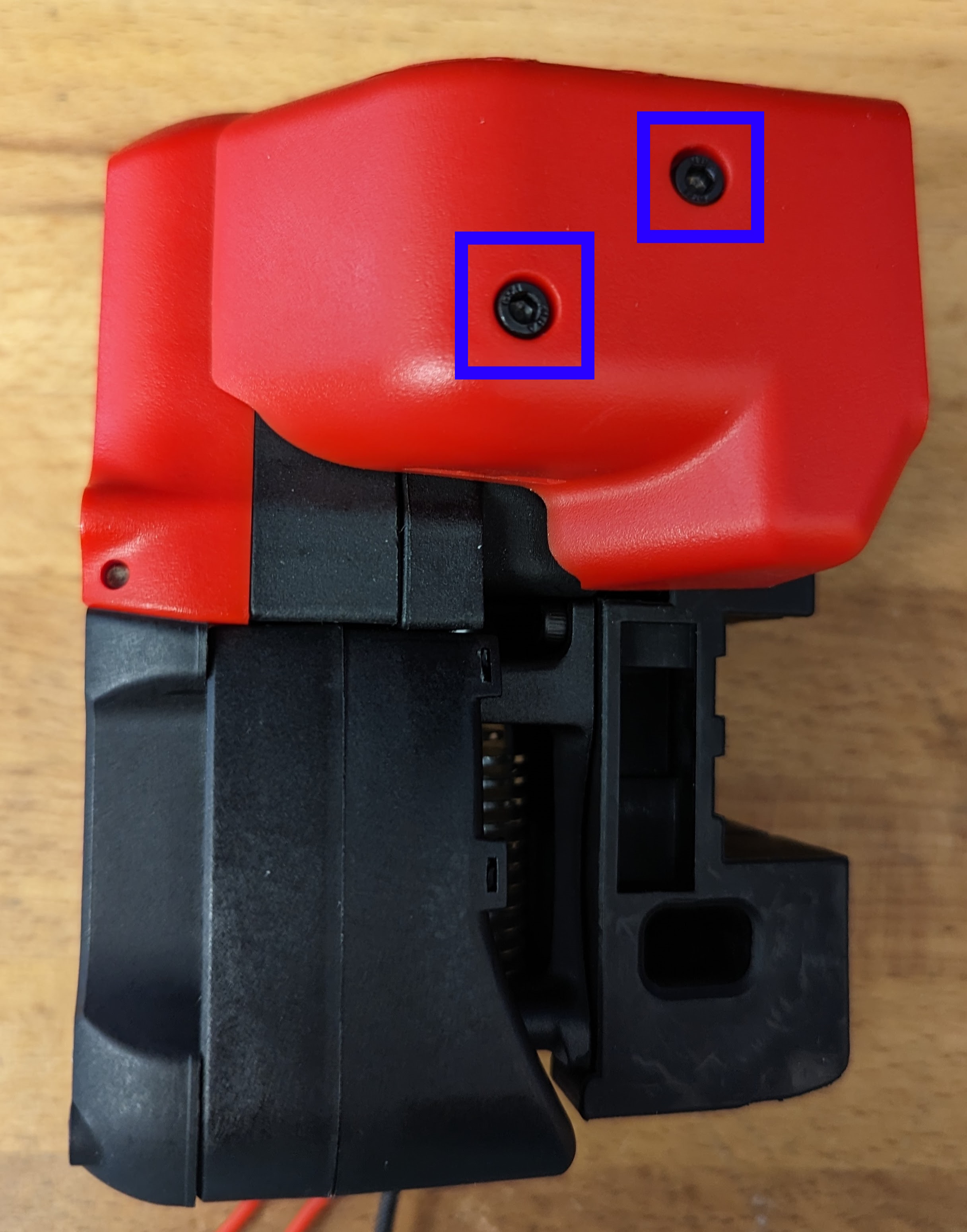
Remove the 2 x M3x8 Screws securing the PCB cover in place and put both the cover and the screws to one side.
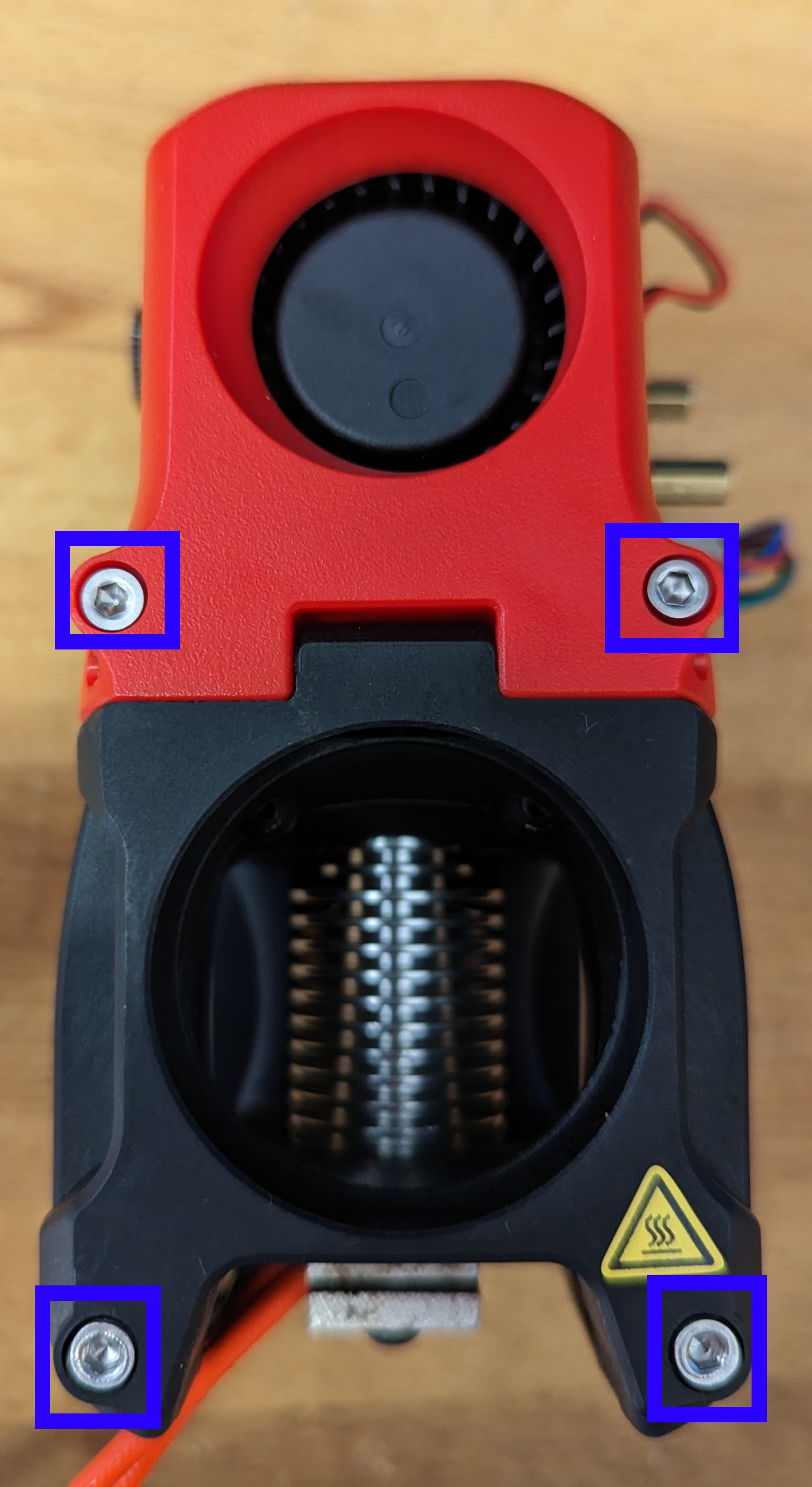
Remove the 2 x M3x12 Screws and 2 x M3x30 Screws securing the fan cover in place. Disconnect the fans.
Remove and keep the 40mm hotend cooling fan (if not part of purchased parts) for installation in the Stealthburner.
Disconnect everything else from the toolhead PCB. Disconnect the toolhead PCB from the cable chain and put to one side for reinstallation.
Remove the 2 x M3x40 Screws securing the printhead to the carriage and remove the printhead.
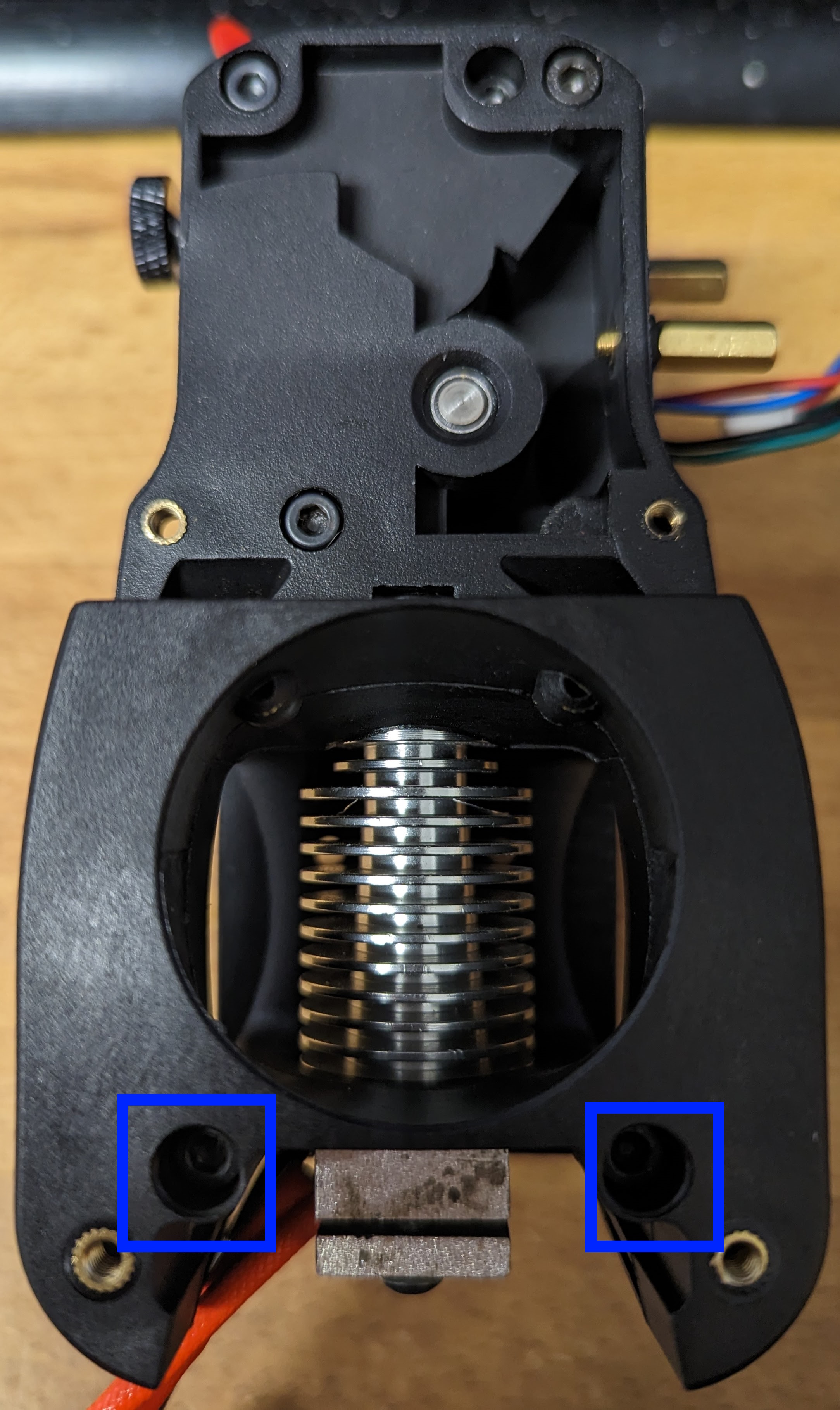
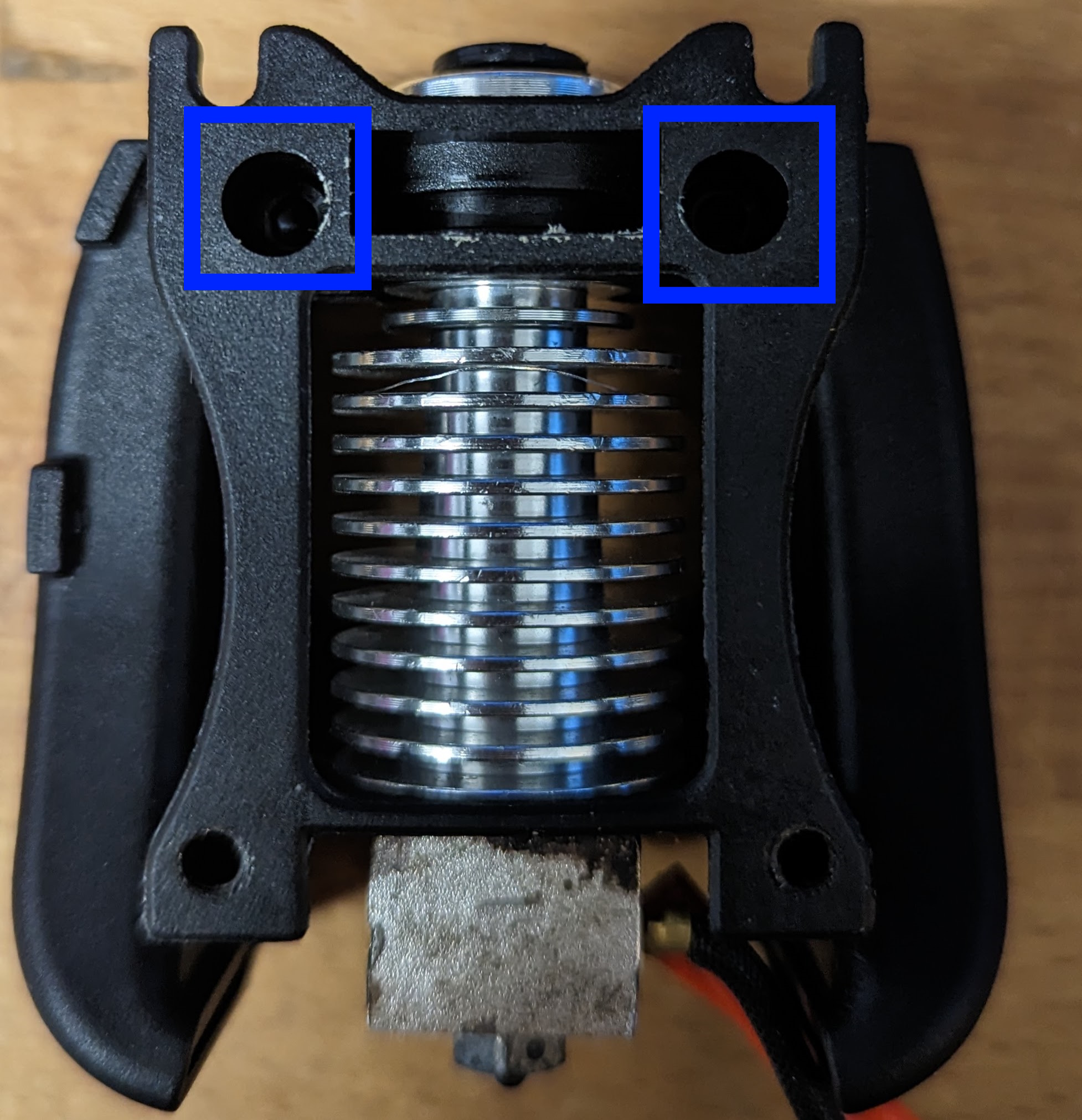
Remove the V6 from the printhead by removing the 2 x M3x20 Screws. Keep the screws as they will be needed during assembly.
Remove the screws securing the cable chain to the rear of the motor. Also remove the cable tie securing the cable chain in place.
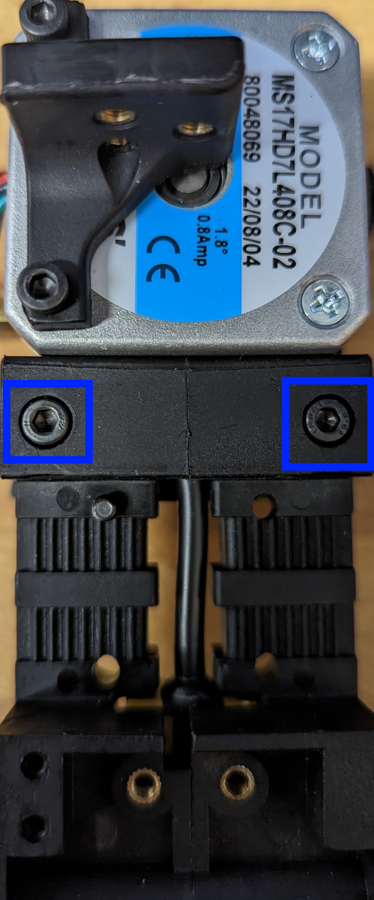
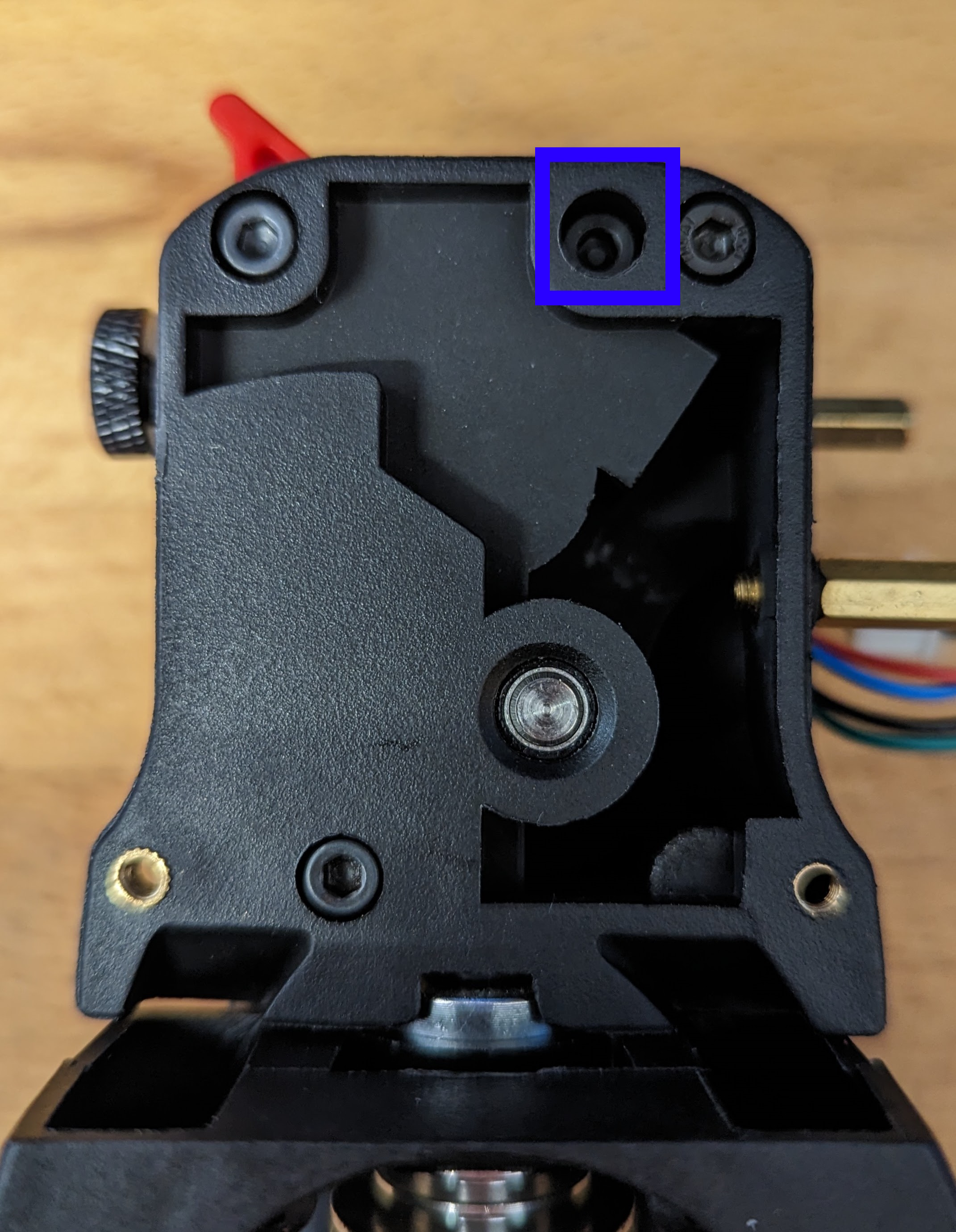
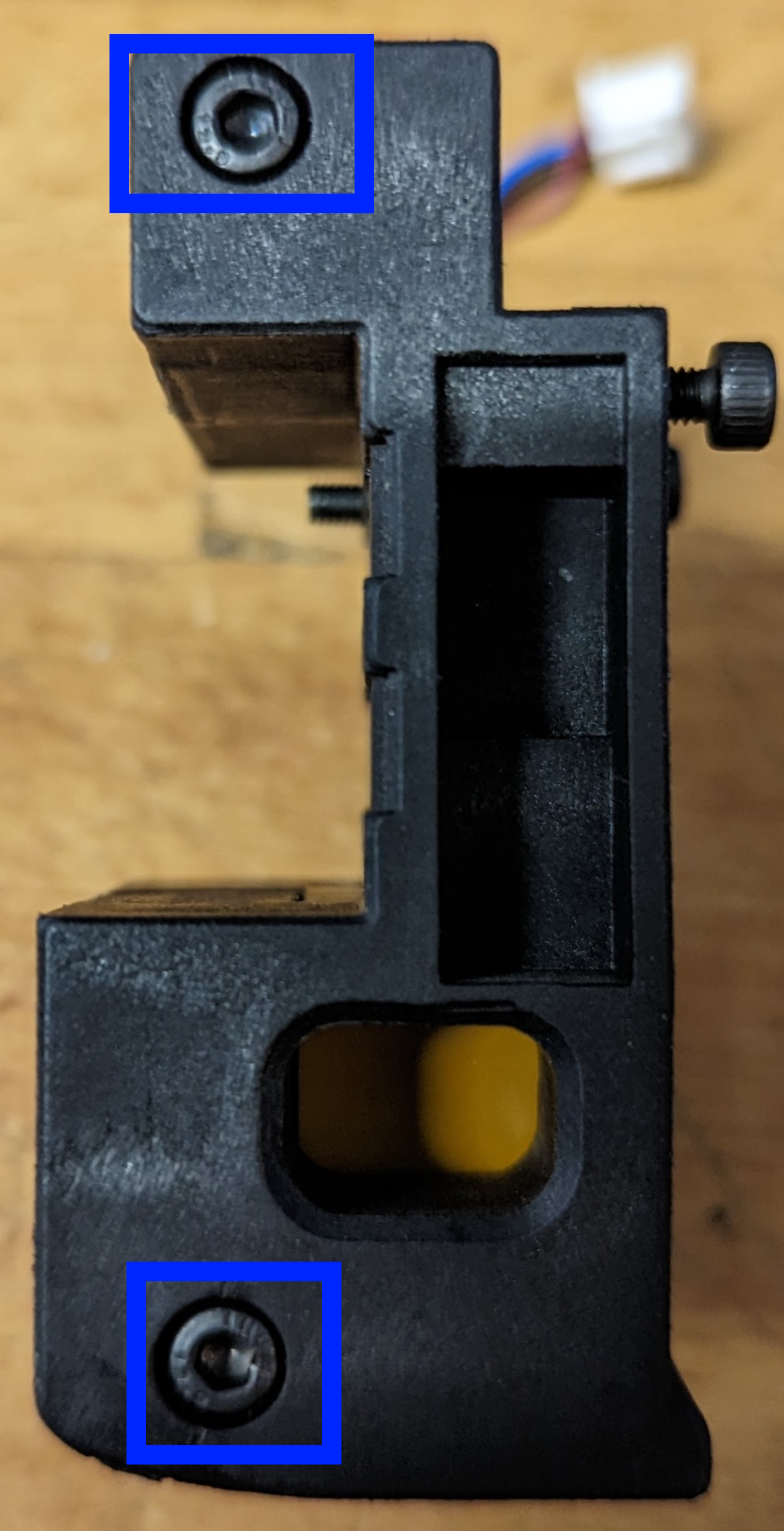
Lift the cable chain out of the way and remove the 2 M3x20 screws securing the extruder in place. Lift the motor up to remove it.
Remove the M3x20 securing the latch in place. Remove the latch.
Remove the M3x30 securing the guider in place. Remove the guider.
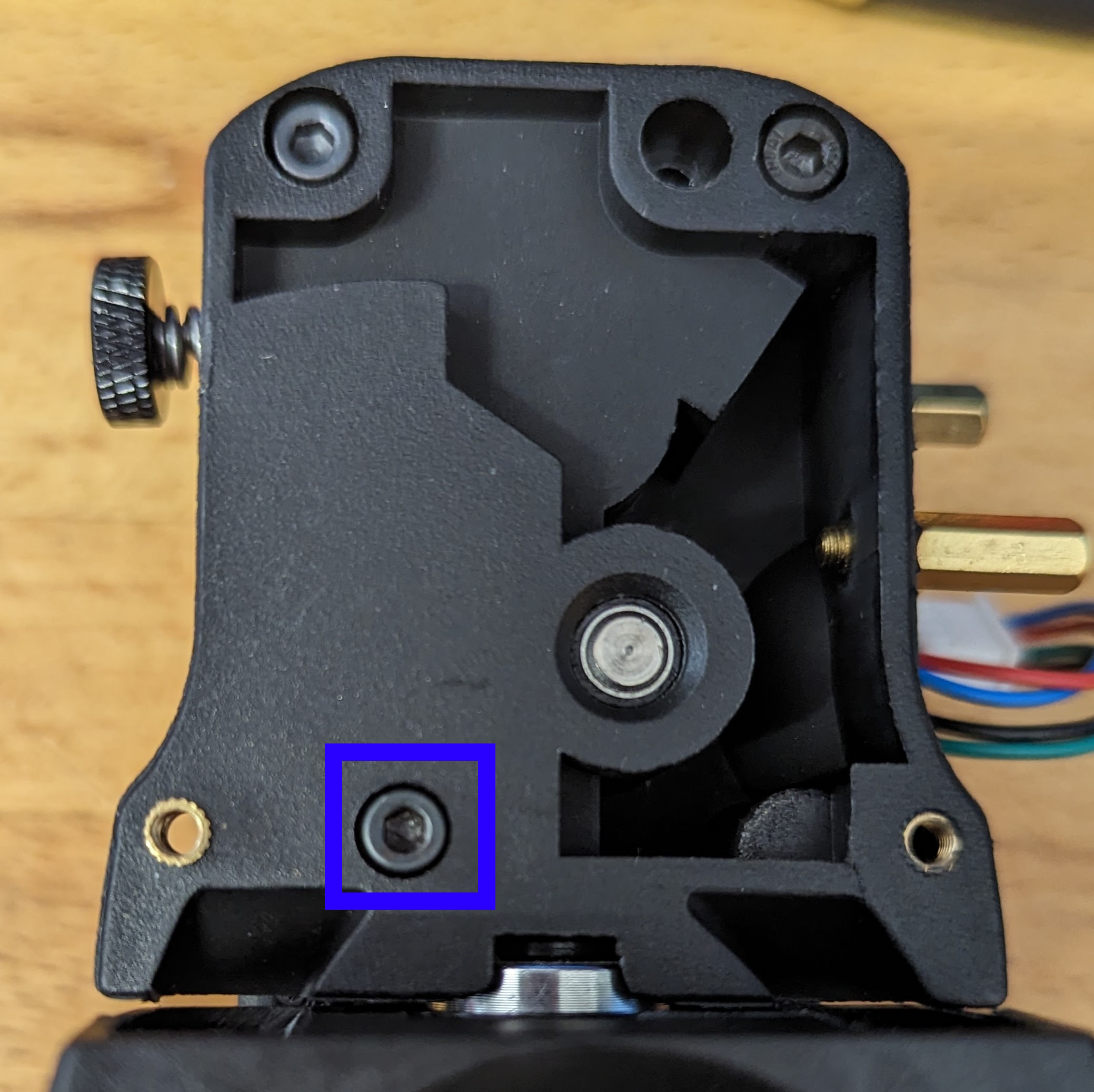
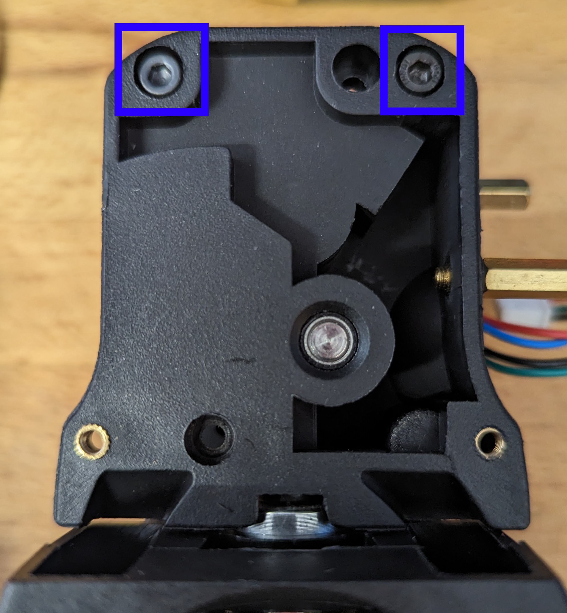
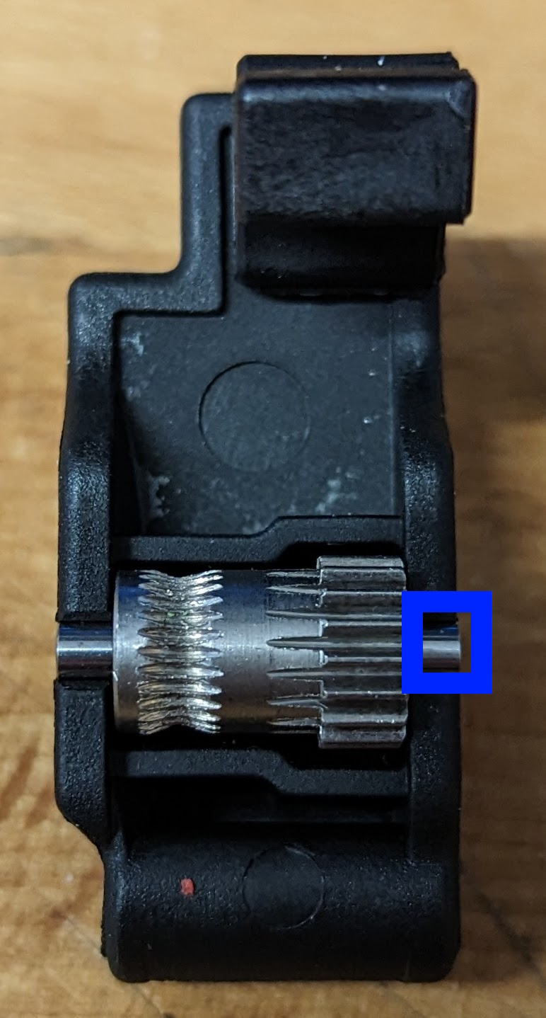
Remove the 2 x M3x30 securing the main body in place. Remove the main body and the drive gear. The MR85 from the motor plate may come away with the drive shaft (which is fine).
Remove the BMG type gear from the guider by pushing out the pin. It is suggested that you use the drive shaft and gears from the Troodon V2 as they are hardened, rather than what you get in the kit.
Remove the 2 x M3 screws securing the probe in place and remove the probe from the carriage.
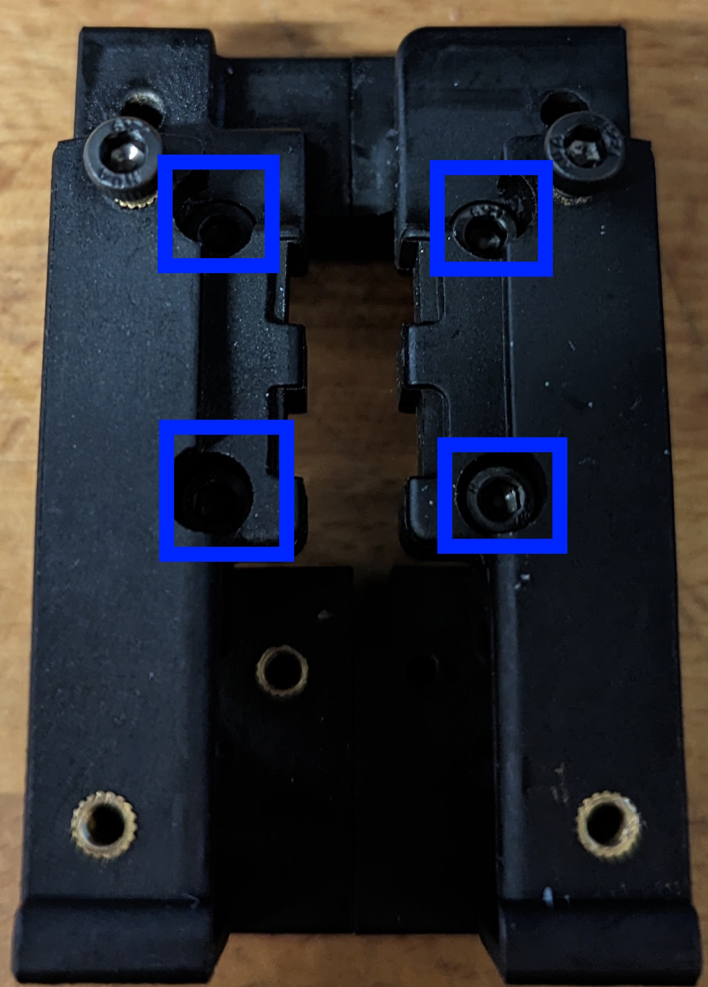
Remove the 2 x M3 screws holding the carriage together.
Remove the 4 x M3 screws securing the carriage to the rail and remove the 2 carriage pieces, separating them from the belts.
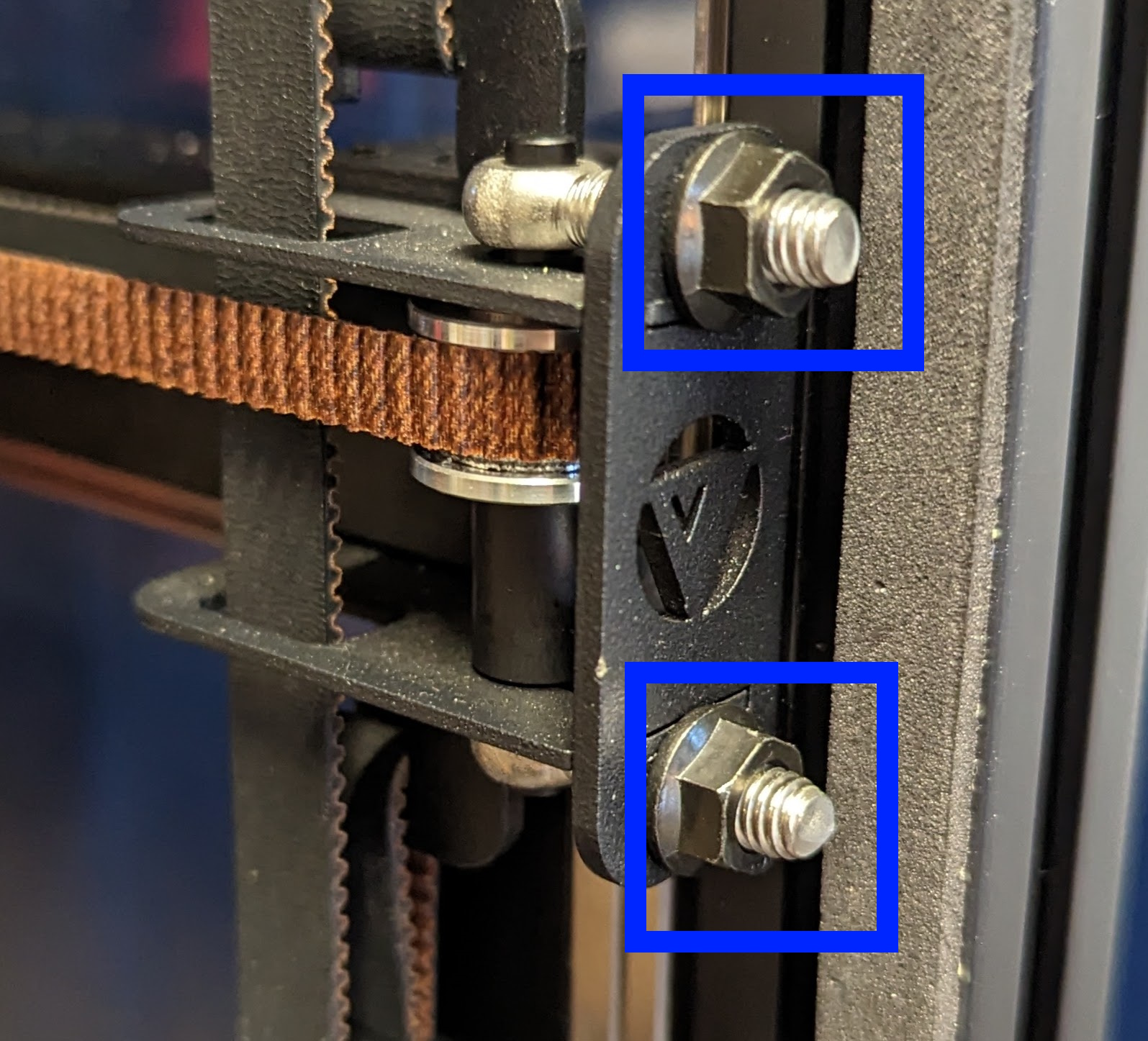
Slacken the belt tighteners so 1 thread is showing in preparation for assembly.
Assembly
Follow the Stealthburner Manual for assembly instructions.
Tighten the belts as detailed here