Overview
This page covers any general information for the Fly-ProX10 H723 board.
It is currently available through AliExpress.
Although the board comes with a socket for a CM4 module, this board can’t be used in SBC mode with RRF due to lack of required connections between the CM4 and the STM32H723 MCU.
The correct SD Card socket to use with RRF is the one next to the STM32H723 MCU.
Driver Power
Make sure you install a jumper for each driver to denote where they are powered from, i.e. either from the HVIN connector or the VIN connector.
Driver Diag Pin
Each board has a jumper for the diag pin just beneath the driver socket. This needs to be installed to use sensorless homing and stall detection.
Please also note the diag pin for driver 9 is shared with the probe pin on the BLTouch header. The remainder of the diag pins are shared with the IO connectors.
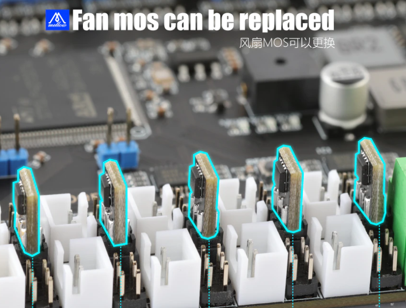
Fan Mosfets
The Fly-ProX10 H723 has a unique feature in that the fan mosfets are replaceable. Each mosfet (VS3622e) controls two of the fan outputs. The orientation that the fan mostfet is plugged into the board doesn’t matter.
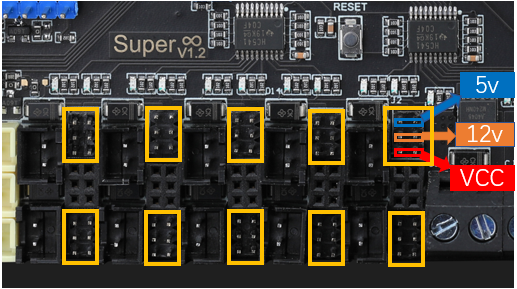
Fan Voltage
The fan voltage can be set using jumpers to either 5v, 12v and Vin.
Set them as shown below.
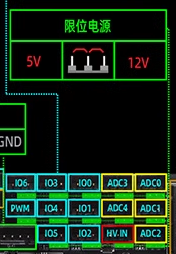
IO Output Voltage
The IO output voltage can be set to either 5v or 12v and is set using the 3 pin header underneath each IO.
Maximum HV Input voltage
The driver sockets have been tested with 48v.
Thermistor Connection
Thermistors should use the ADC inputs. The thermistors should be connected between ground and the signal pin.
Initial Installation
The board that you will receive doesn’t have any firmware installed so when plugged into a computer, the board will show as an unidentified device. Follow the WiFi instructions.