Overview
The only type of accelerometers that are supported are LIS3DH, LIS3DSH and LIS2DW12.
Wiring
It is recommended to use a USB3 cable for the wiring between the board and the accelerometer.
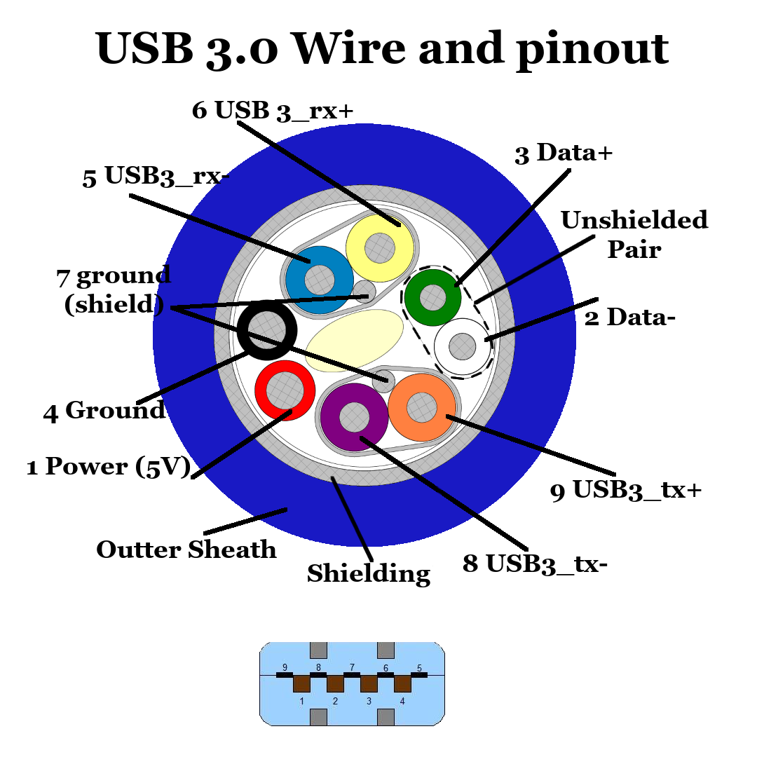
The colours used in the table below match the colour coding above.
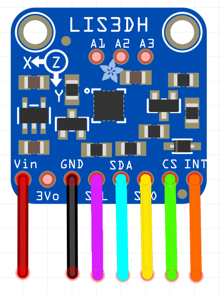
One possible method of connecting the accelerometer to the Fly-Super5Pro H723 is described in the table below. The image can be used to aid in identification.
Because the firmware is so flexible and we’re using software SPI, most pins can be used for this.
These connections are on the EXP2 Header on the board.
Keep in mind some modules (E.g. the purple ones from ebay or aliexpress) don’t have a voltage regulator, connect them to 3.3 V and check the voltage before plugging it in.
| Accelerometer Image Wire Colour | Accelerometer Pin Name | Accelerometer Pin Type | Fly-Super5Pro H723 Pin |
|---|---|---|---|
| Red | VIN / VCC | Supply Voltage | 3.3V / 5V |
| Black | GND | Ground | GND |
| Purple | SCL | SPI SCK | PB_3 |
| Blue | SDA | SPI MOSI | PB_5 |
| Yellow | SDO | SPI MISO | PB_4 |
| Green | CS | Chip Select | PB_6 |
| Orange | INT / INT1 | Interupt | PD_6 |
Mounting the LIS3DH
The accelerometer should be mounted firmly to the tool. For a bed slinger (such as an ender 3), it should also be possible to mount it to the bed to take readings for the Y axis.
Board.txt Changes
Add the following to board.txt.
If you don’t have a board.txt file, it can be added in the sys folder (same folder that config.g goes in) using DWC.
accelerometer.spiChannel = 2
Config.g Changes
Your config.g should be modified as below.
M955 P0 C"PB_6+PD_6" I20
The I (orientation) parameter tells the firmware which of the 24 possible orientations the accelerometer chip is in relative to the printer axes. It is expressed as a 2-digit number.
The first digit specifies which machine direction the Z axis of the accelerometer chip (usually the top face of the chip) faces, as follows: 0 = +X, 1 = +Y, 2 = +Z, 4 = -X, 5 = -Y, 6 = -Z. The second digit expresses which direction the X axis of the accelerometer chip faces, using the same code. The direction of positive X is printed on the circuit board. If the board was mounted in the orientation shown in the above image, with +X of the machine being to the right, Y+ being behind and Z+ being up, the I value would be 54. This document gives information regarding the I value for the new Duet toolboard with accelerometer.
20 is the default orientation if no orientation has been specified.
DWC Plugin
There is an input shaper plugin to capture and analyse the data. It can be found here
Usage
The accelerometer can be activated using M956