Overview
The Fly-407ZG is an STM32F407ZGT6 based board.
Firmware File
Choose the correct corresponding firmware (firmware-stm32f4-wifi-XXX.bin) from here. Remember to rename it to firmware.bin. Put it in the root of a FAT32 formatted SD card. The maximum size supported card is 32GB.
TeamGloomy/Mellow Adapters
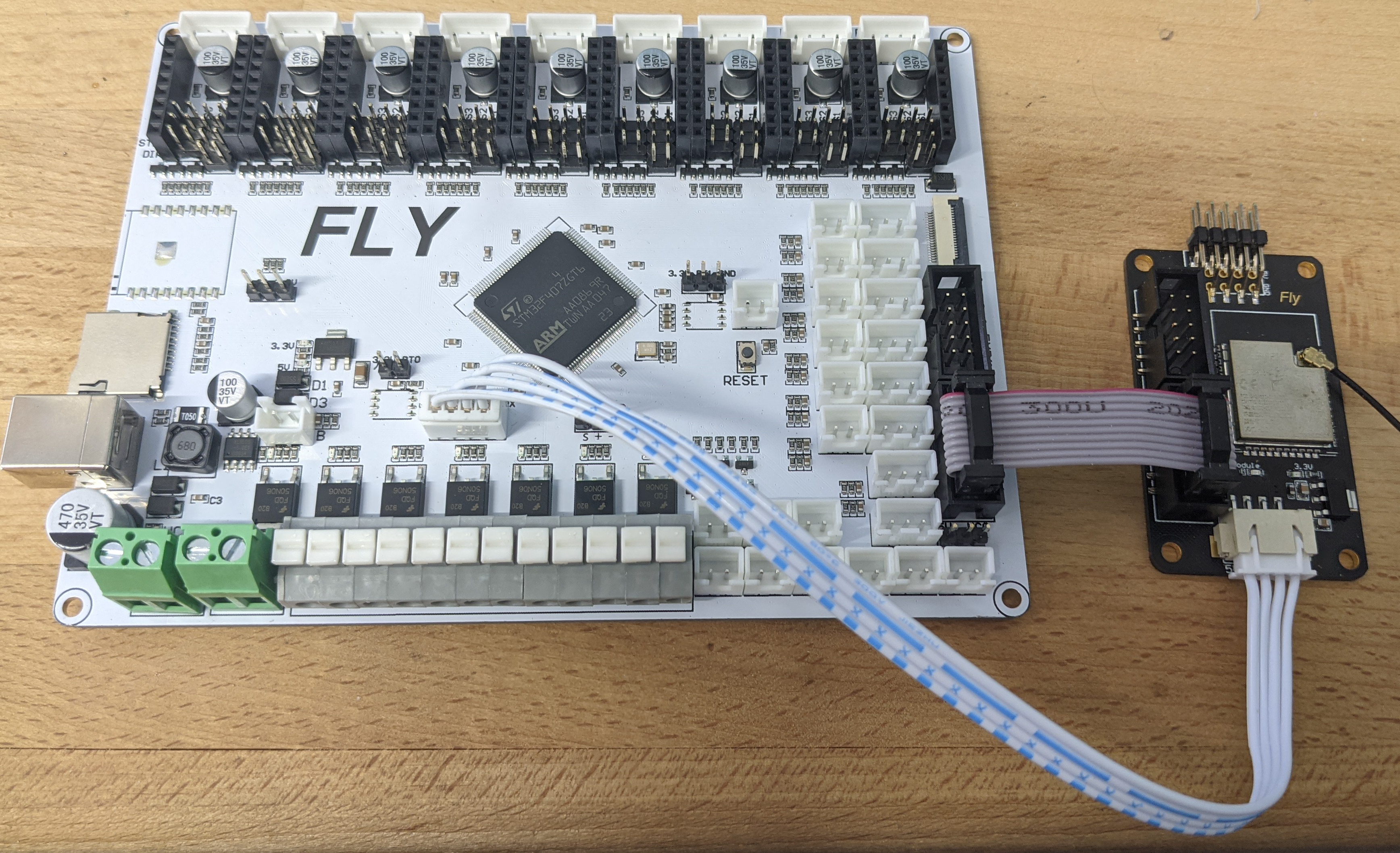
TeamGloomy and Mellow have teamed up to produce ESP32 adapters.
They can be purchased through aliexpress.
Connect the ESP32 Adapter to the board as shown below.
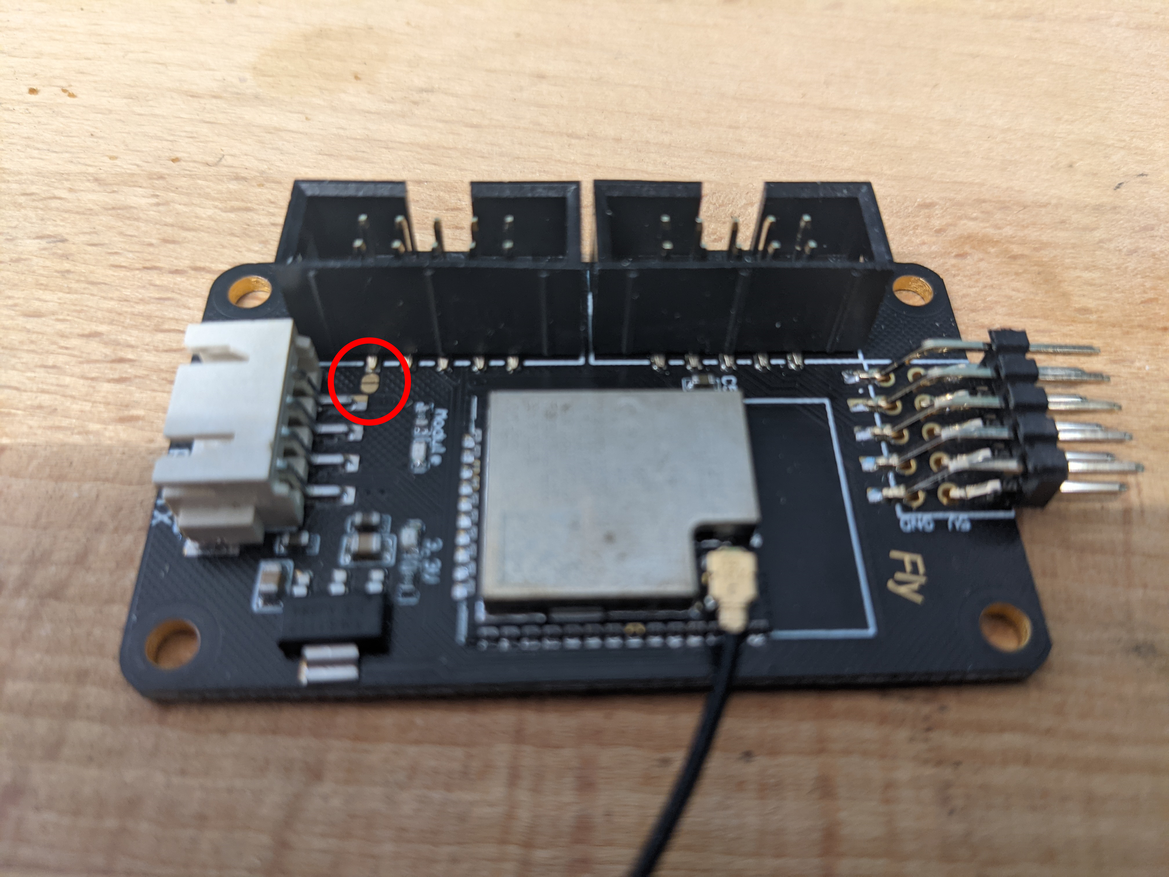
If not connecting the 4-pin serial cable, then add a small amount of solder in the area highlighted below.
Homemade ESP32
Use an ESP32 with USB programming as it already 5v tolerant and it allows for updating via USB. They also need to be the 36 pin variety so they have GPIO0 broken out.
BOM
- 1 x 36 pin ESP32
- 1 x 330R resistor
- jumpers or other ways of connecting to the Fly-407ZG
Preparing the ESP32
Follow the instructions here.
Connecting the ESP32
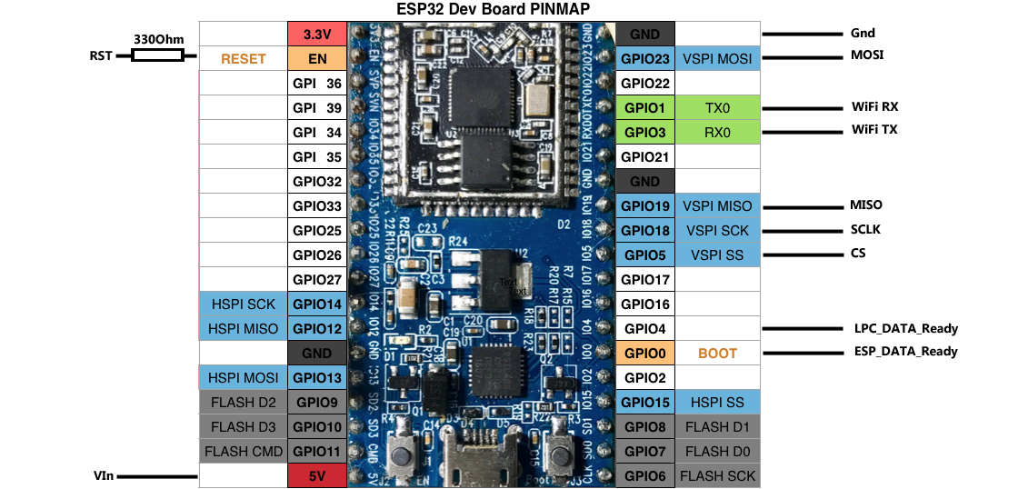
The pinout for the Fly-407ZG can be found here and the schematic for the Duet 2 WiFI for reference can be found here.
The table below shows the pins required on the ESP32 and what they are connected to on the Fly-407ZG. Please ensure that your cables are no longer than 30cm although they should ideally be as short as possible.
| ESP32 Pin | Fly-407ZG Pin | Resistor Value |
|---|---|---|
| RST | PB_2 on EXP2 | 330R |
| VSPI SS/GPIO5 | PF_11 on EXP2 | None |
| VSPI MOSI/GPIO23 | PB_15 on EXP2 | None |
| VSPI MISO/GPIO19 | PB_14 on EXP2 | None |
| VAPI SCK/GPIO18 | PB_13 on EXP2 | None |
| ESP_DATA_Ready/GPIO0 | PC_5 on EXP2 | None |
| LPC_DATA_Ready/GPIO4 | PC_4 on EXP2 | None |
| VIN(5v) | 5v on EXP2 | None |
| GND | GND on EXP2 | None |
Prepare the SD Card
Follow the instructions on Getting Started with RRF3
Board.txt file
You will also need a board.txt file in the sys folder. Below are the contents that should be used.
//Config for Fly-407ZG
board = fly_f407zg
8266wifi.espDataReadyPin = PC_5
8266wifi.TfrReadyPin = PC_4
8266wifi.espResetPin = PB_2
8266wifi.csPin = PF_11
heat.tempSensePins = { PF_3, PA_0, PC_1, PC_0, PF_10, PF_5, PF_4 }
Updating the ESP32 by RRF
If you have an ESP32 WiFi adapter that supports updating via RRF, you need to add the following information to the board.txt file.
8266wifi.serialRxTxPins = { PA_10, PA_9 }
serial.aux.rxTxPins = { NoPin, NoPin }
Smart Drivers
If using TMC5160 or TMC22XX drivers (where 22XX is either the TMC2208, TMC2209, TMC2225 or TMC2226), the following line must also be added to the board.txt file
stepper.numSmartDrivers = X
Where X is the number of drivers fitted in total.
TMC22XX UART Drivers
The drivers must be continuous and start at unit 0 (unless TMC5160 are also used, which case they must be installed after them). So, for the SKR board, if you have say 3 TMC2208s and 1 other driver, the 2208s must be in slots 0, 1, 2 and the remaining driver in slot 3 or 4. You can use RRF to assign any of those slots to an axis/extruder.
TMC5160 SPI Drivers
The Fly-407ZG is the only STM32 board that can’t be used with 5160 drivers when using an ESP8266 WiFi adapter using the standard connection method. This is due to them sharing the SPI pins used to also gain SBC support. You need to connect the ESP8266 via the alternative method.
Sensorless Homing
To be able to use sensorless homing on this board, a jumper cable needs to be installed between the diag pin of the driver and an endstop input.
For more information about setting up sensorless homing, please read this.
Board.txt Location
Place the board.txt file in a directory called “sys” on the SD card and install the SD card in the Fly-407ZG.
Final Setup
Once connected, power up the board using 12-24v and connect to the USB port on the board. Using a program such as putty. Follow the instructions here to set it up for RRF.
text
M997 S1
Wait for the uploading of the WiFi firmware to finish. Then send the following
text
M552 S-1
Continue with the instructions below.
M552 S0
M587 S"your SSID" P"your password"
M552 S1
If you wanted to use “PassWord”, you would write P”P’a’s’sW’o’r’d” with the ‘ indicating the following letter should be lower case. Explanation here.
The blue light on the WiFi chip shoould then flash blue and will go solid when a connection has been established. The ip address will be shown on the serial connection. It is also possible to type just M552 to get the current ip address reported back.
The final thing to do is add the line “M552 S1” to your config file. This can be done through the web interface. This just ensures that the WiFi connection is started at start up. There is no need to add the M587 command as this is written permanently to the flash of the ESP8266 chip.
Once up and running
You will need to PID tune your tools and your bed. Please be aware that bed tuning may take up to an hour and tool tuning normally takes around 15 minutes. If it takes longer, that is also fine as up to 30 cycles may be ran.
To tune the bed, run the following command, changing the temperature (the S value) if a different tuning temperature is required.
M303 H0 S60
To tune each tool, run the following command, changing the temperature (the S value) if a different tuning temperature is required. This proceedure will activate the part cooling fans during the final phase of the tuning process so their effect is taken into account. If your printer has more than one tool, make sure each one of them is tuned.
M303 T0 S220
Once the tuning is complete, either copy the M307 command into the heater definitions or send M500, ensuring you have M501 at the end of your config.g.
If the tuning fails at the end, carry on saving the values as in most cases the outputted values still work correctly.
If the values still result in a heater fault, please refer to this wiki page for information about how to adjust the values manually.