Overview
This page covers any general information for the Fly-RRF-36 toolboard.
It is currently available through AliExpress.
This toolboard is only supported from firmware version 3.5 beta 4 and above.
The Fly-RRF-36 is the first RP2040 based toolboard compatible with both Duet 3 boards and STM32H723, STM32H743 and STM32F4 boards with spican modules running 3.5 beta 4 and above.
Hardware Overview
| Processor | Raspberry Pi RP2040 |
| Processor Features | Dual ARM Cortex-M0+ @ 133MHz, 264kB on-chip SRAM |
| Networking/Comms | CAN-FD, USB Serial Port |
| On-board stepper driver | 1 x TMC-2209 |
| Stepper driver features | Up to 1.6A peak current, microstep interpolation from any setting to x256, stall detection, stealthChop2 |
| High current outputs | 1 x 10A, VIN voltage only |
| Thermistor/PT1000 inputs | 1 x input, optimised for 100k thermistors and PT1000 sensors, 1 x onboard NTC3950 |
| PT100 | Can be purchased with a PT100 amplifier onboard with support for 2-wire, 3-wire and 4-wire PT100 temperature sensors |
| Medium current outputs | 2 x 2-pin fan outputs, voltage selectable between VIN, 12V and 5V. 1A max per output |
| Inputs/Outputs | 3 x on-board I/O connectors for endstop, switches, filament monitor, Z probe. 1 x servo output. |
| Accelerometer | Integrated LIS3DH accelerometer |
| Power monitoring | VIN voltage reporting |
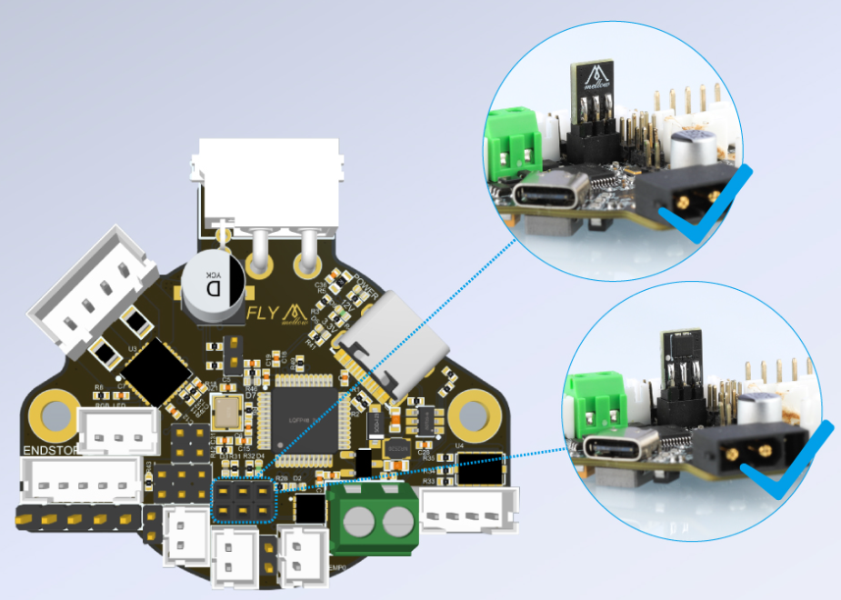
Fan Mosfets
The Fly-RRF-36 has a unique feature in that the fan mosfet is replaceable. Each mosfet (VS3622e) controls two of the fan outputs. The orientation that the fan mostfet is plugged into the board doesn’t matter.
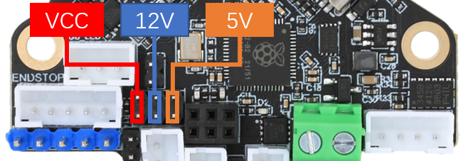
Fan Voltage
The fan voltage can be set using jumpers to either 5v, 12v and Vin.
io1.in Diode
If using io1.in with a simple switch, install a jumper to bypass the diode (marked diode BP on the pinout). Don’t install the jumper if using any electronic probes such as an inductive or optical sensor.
CAN Termination
If using a single toolboard, make sure the CAN jumper is installed, as indicated on the pinout.
If using multiple toolboards, only the last toolboard should have a CAN jumper installed.
PT1000 Support
The hotend temperature sensor input support PT1000. When using one, make sure the PT1000 jumper is installed. Make sure it is removed when using a standard thermistor.
Also make sure you define the resistor value as R1000 in your M308 command.
Initial Firmware Installation
The board that you will receive does come with firmware installed. It is suggested that you reflash the latest firmware anyway as the board you receive may have an older version of the firmware installed.
Download either the Stable firmware file called Duet3Firmware_FLY36RRF.uf2 from here or the latest beta/RC firmware file called Duet3Firmware_FLY36RRF.uf2 from here.
To install the firmware, whilst holding the reset button, plug the Fly-RRF-36 into your PC. Let go of the reset button and drag and drop the .uf2 file onto the rpi drive that appears. Follow the CAN Connection instructions to continue.
Updating the Toolboard Firmware before 3.5.0-rc2
Download either the Stable firmware file called Duet3Firmware_FLY36RRF.uf2 from here or the latest beta/RC firmware file called Duet3Firmware_FLY36RRF.uf2 from here.
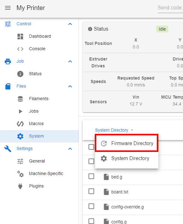
Using DWC, upload the .uf2 firmware file to the system tab.
Navigate to the firmware folder.
Change the name of the file from Duet3Firmware_FLY36RRF.uf2 to Duet3Firmware_FLY36RRF.bin.
Upload the .uf2 file again.
Send M997 B124 and it will update (This assumes your board is the default CAN address 124, change the address in the command if necessary). The updating time (around a minute or two) is longer on RP2040 based toolboards so be patient.
Updating the Toolboard Firmware from 3.5.0-rc2 Onwards
Using DWC, upload the latest firmware file to the system tab. Once uploaded, send M997 B124 and it will update (This assumes your board is the default CAN address 124, change the address in the command if necessary). The updating time (around a minute or two) is longer on RP2040 based toolboards so be patient.