Overview
The below describes an alternative method of connecting an ESP8266 to the Fly-407ZG.
There are two different methods. One frees up the EXP2 header only and the other frees up both the EXP1 and EXP2 headers.
This alternative modification provides 3 advantages.
* SPI controlled drivers (TMC5160) can be used
* EXP2 (method 1) or both EXP1 and EXP2 (method 2) are freed up for other uses
* Both RRF updating of the ESP8266 and serial displays can be used at the same time   This will involve soldering some cables to the board.
BOM
- 1 x ESP8266 adapter (any of the 3 types will be suitable)
- Some cable
Connecting the Adapter
This example uses the Fly WiFi Adapter but the instructions are applicable to all 3 types.
Method 1
Method 1 Cables to solder to the Fly-407ZG
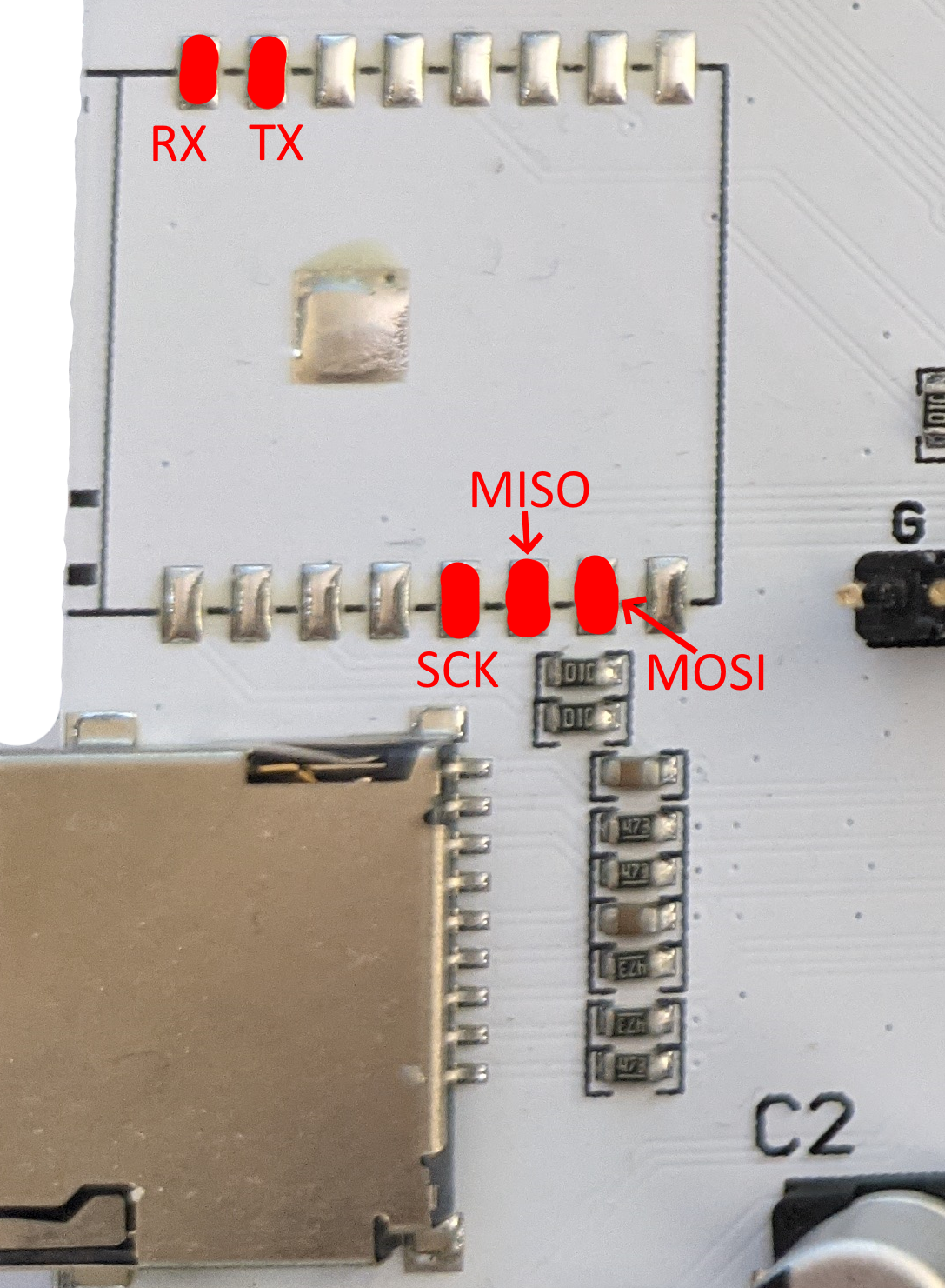
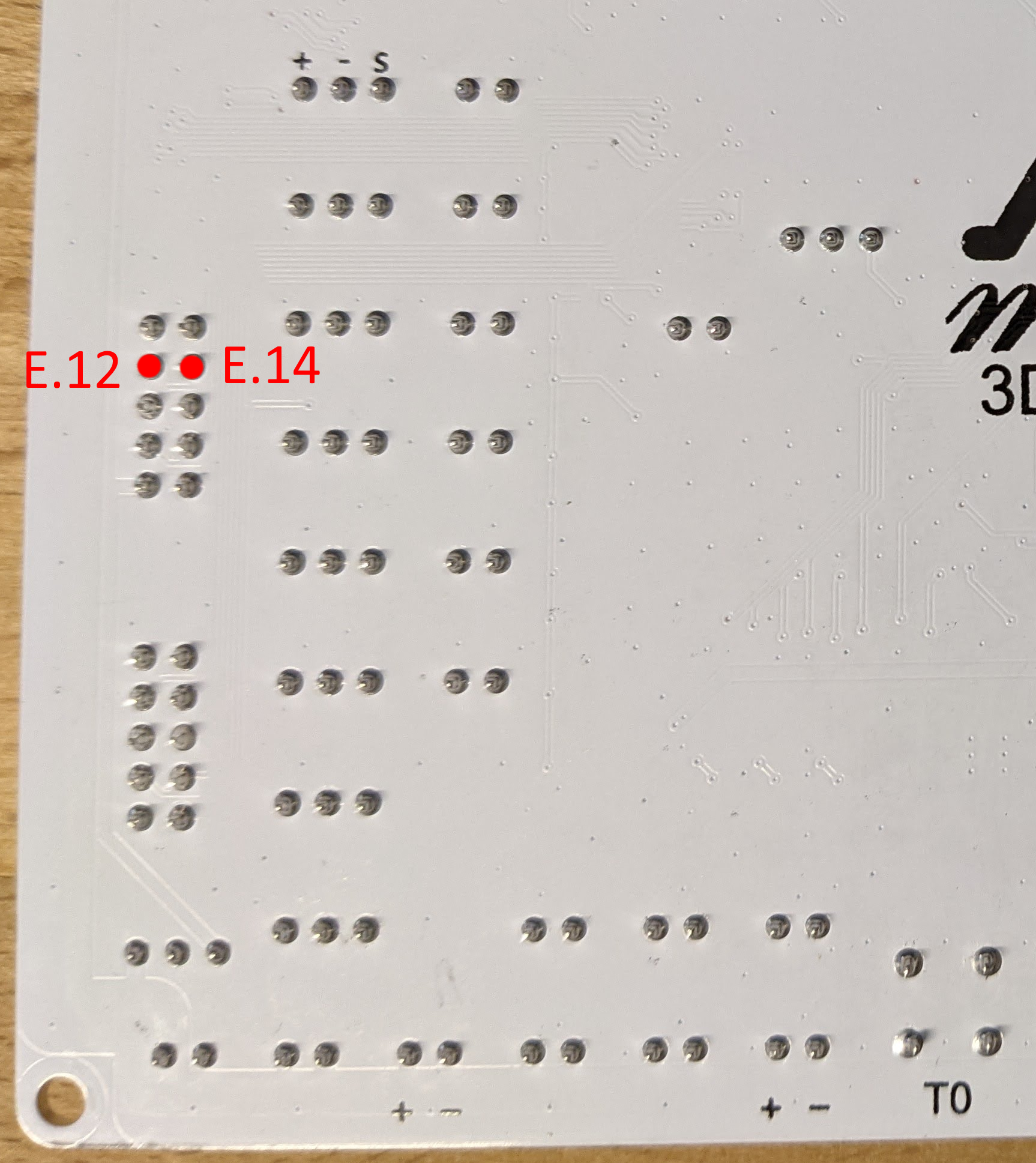
7 cables are to be soldered to the board. 5 of these are on the onboard ESP pads and the other 2 are on the EXP1 connectors.
Connect the 5 cables to the Fly-407ZG as shown below
Connect the 2 cables to the Fly-407ZG as shown below
Method 1 Cables to solder to the Adapter
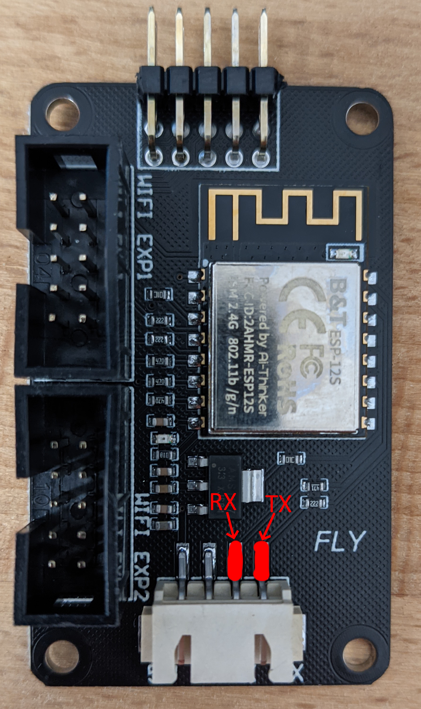
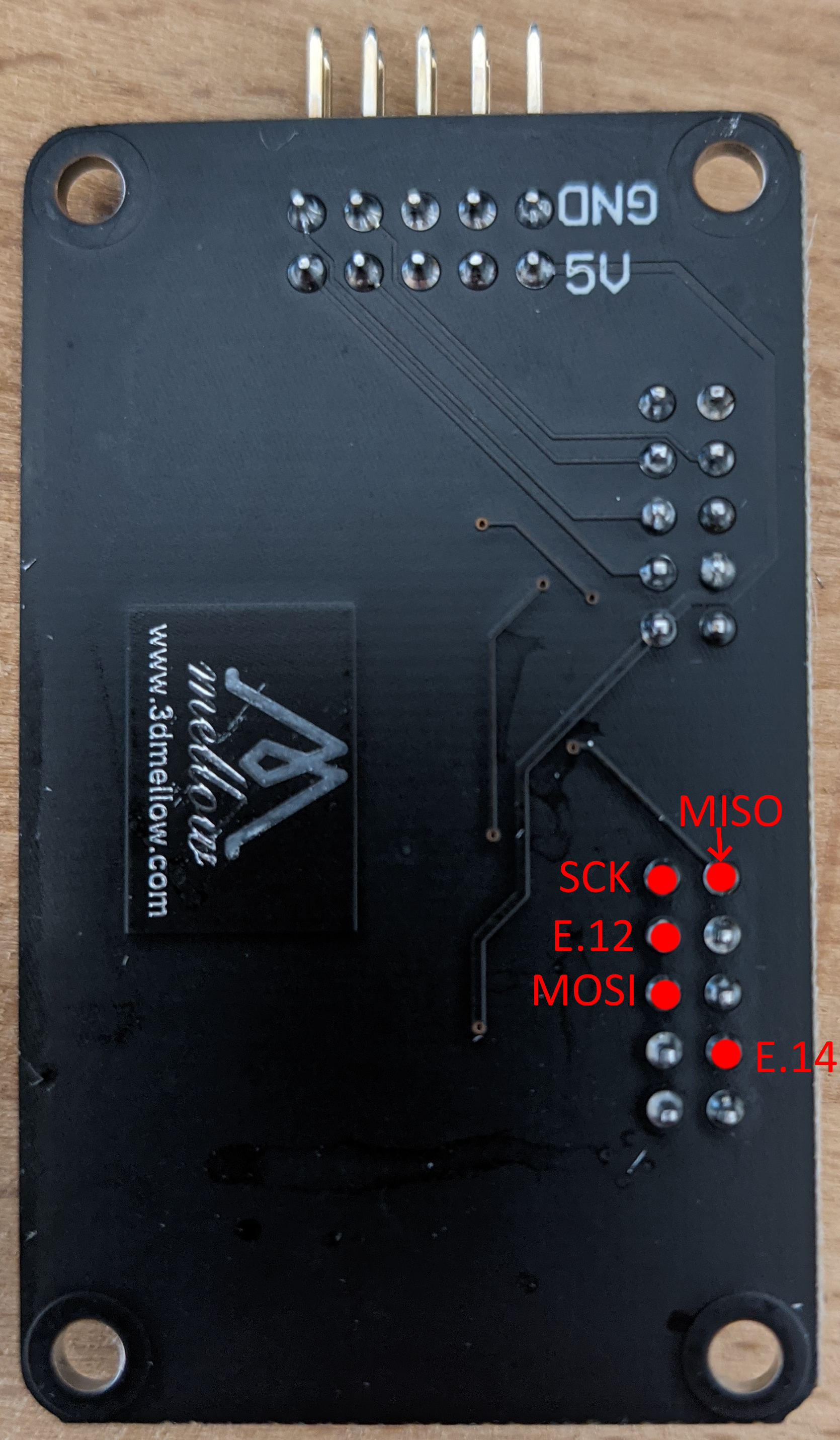
The 7 cables soldered to the Fly-407ZG then need to be attached to the adapter.
2 of the 5 cables should be attached as shown below. The RX cable from the Fly-407ZG should be connected to the TX pad on the adapter and the TX cable from the Fly-407ZG should be connected to the RX pad on the adapter.
The remainder of the cables are to be connected to the adapter as shown below.
Method 1 Other Connections
Connect a cable between EXP1 on the Fly-407ZG and the adapter.
Method 1 Board.txt Changes
The following changes should be made to the board.txt file
//ESP8266 Settings
8266wifi.espDataReadyPin = PE_15;
8266wifi.TfrReadyPin = PB_10;
8266wifi.espResetPin = PE_14;
8266wifi.csPin = PE_12;
SPI2.pins = {PB_3,PB_4,PB_5}
8266wifi.spiChannel = 2
8266wifi.serialRxTxPins = { PG_9, PG_14 } ;
Method 2
Method 2 Cables to solder to the Fly-407ZG
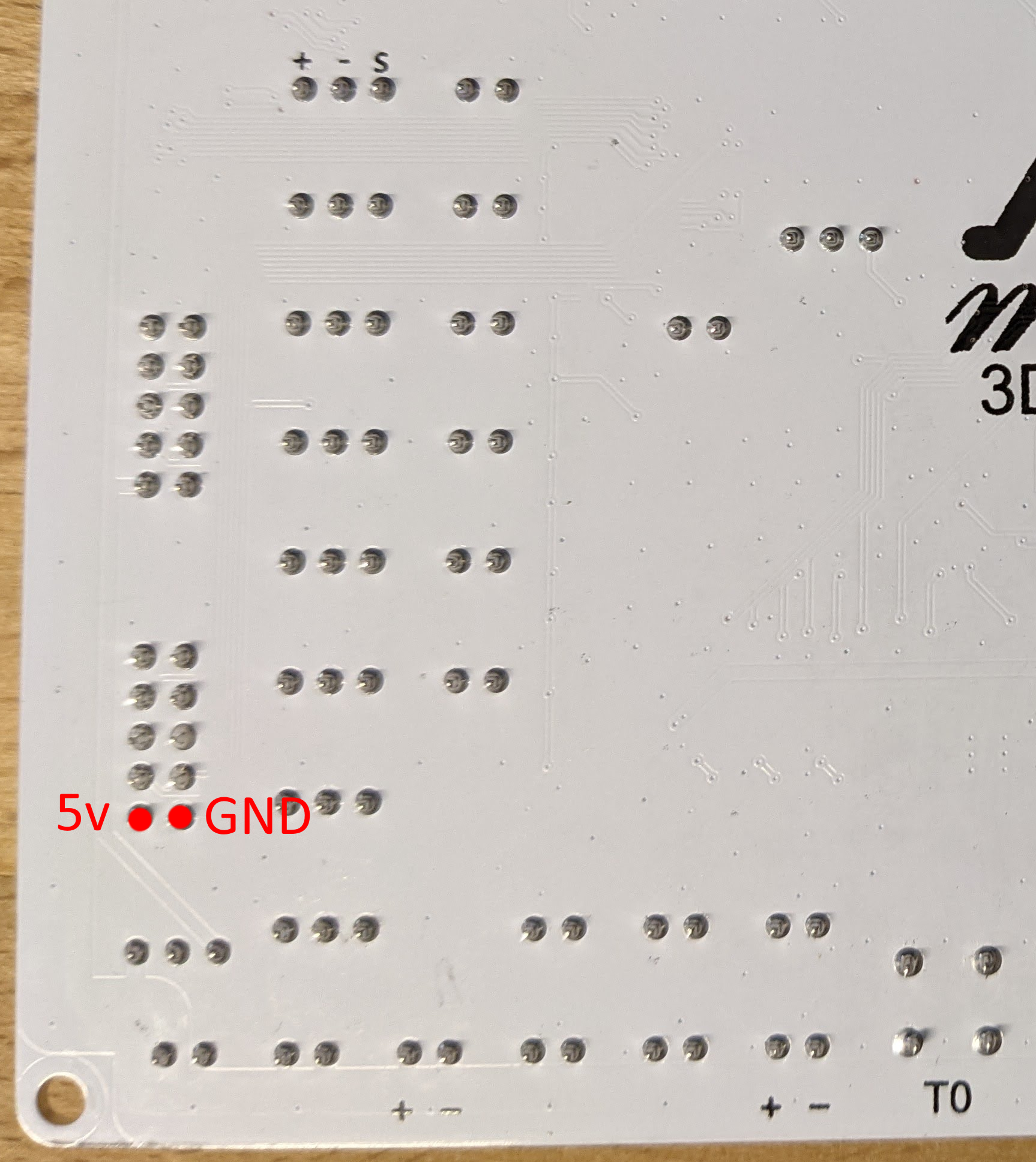
11 cables are to be soldered to the board. 6 of these are on the onboard ESP pads, 3 to the eeprom and MAX6675 connections and 2 to EXP1.
Connect the 6 cables to the Fly-407ZG as shown below

Connect the 3 cables to the Fly-407ZG as shown below
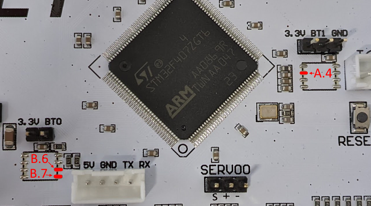
Connect the 2 cables to the Fly-407ZG as shown below
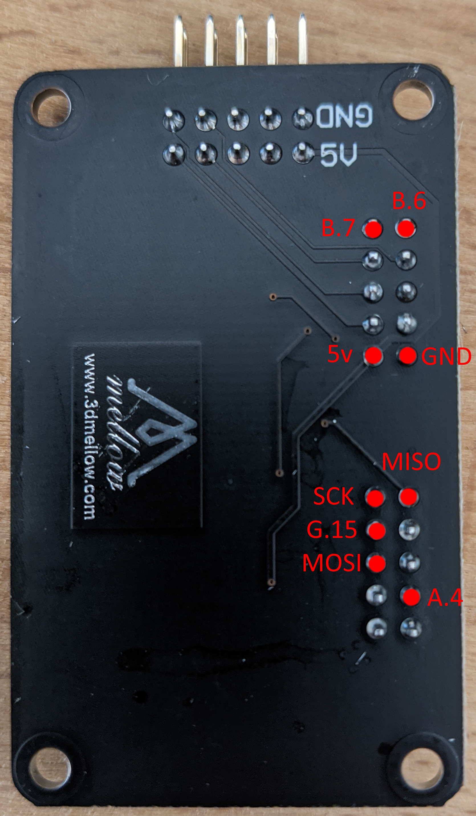
Method 2 Cables to solder to the Adapter
The 11 cables soldered to the Fly-407ZG then need to be attached to the adapter.
2 of the 11 cables should be attached as shown below. The RX cable from the Fly-407ZG should be connected to the TX pad on the adapter and the TX cable from the Fly-407ZG should be connected to the RX pad on the adapter.
The remainder of the cables are to be connected to the adapter as shown below.
Method 2 Board.txt Changes
The following changes should be made to the board.txt file
//ESP8266 Settings
SPI2.pins={ PB_3, PB_4, PB_5 }
8266wifi.espDataReadyPin = PB_7
8266wifi.lpcTfrReadyPin = PB_6
8266wifi.espResetPin = PA_4
8266wifi.csPin = PG_15
8266wifi.spiChannel=2
serial.aux.rxTxPins = { PA_10, PA_9 }
8266wifi.serialRxTxPins = { PG_9, PG_14 }