Overview
There have been a number of reports of premature bearing failures in the Clockwork1 Extruder fitted to Troodon V2 Printers.
The issue appears to stem from fitting bearings that are rubber sealed rather than steel sealed.
Parts Required
You will need to purchase the following for this modification.
- 2 x MR85-ZZ bearings
- High strength Locking Fluid, such as Loctite 272 (Used to resecure the drive gear)
Disassembly
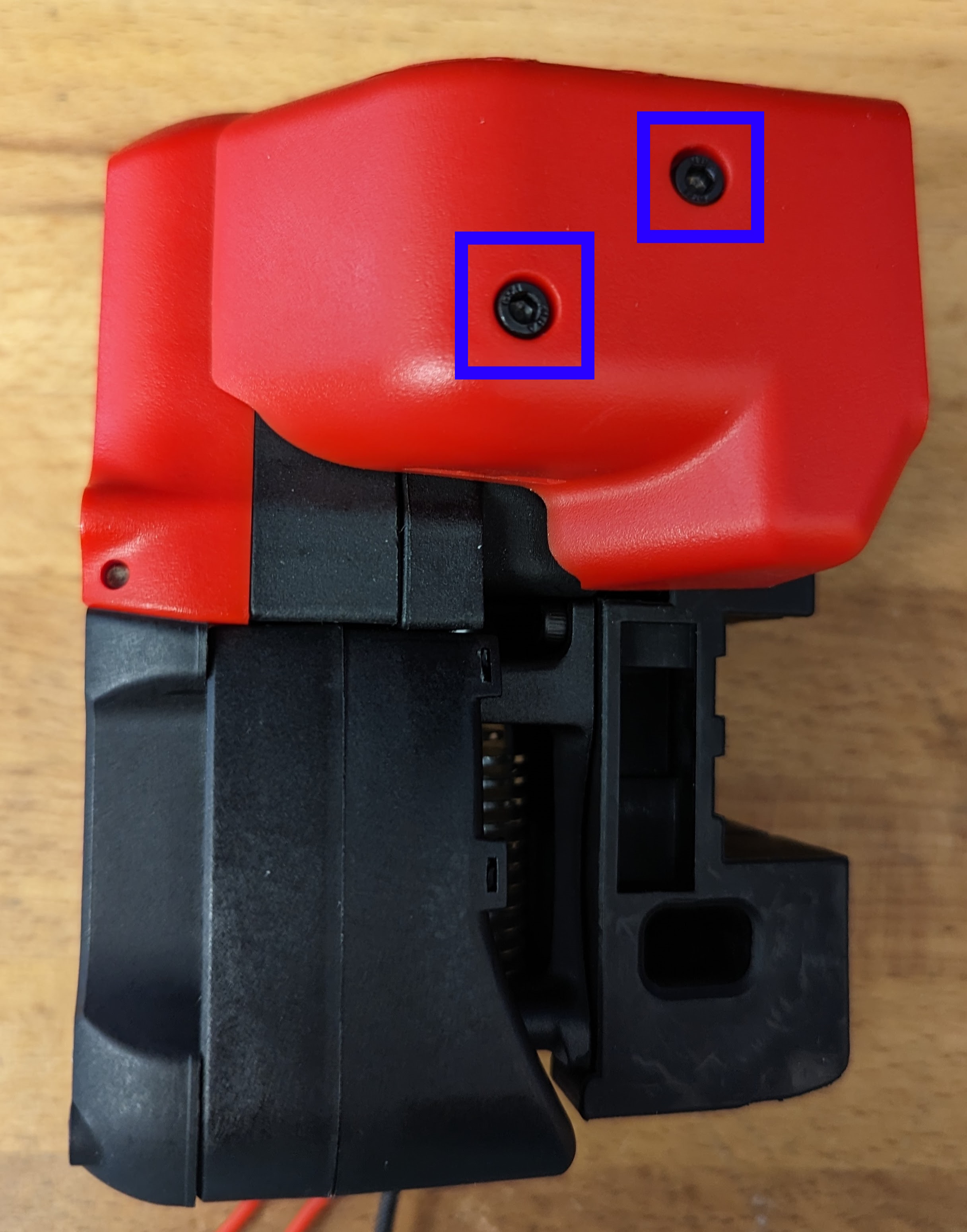
Remove the 2 x M3x8 Screws securing the PCB cover in place and put both the cover and the screws to one side.
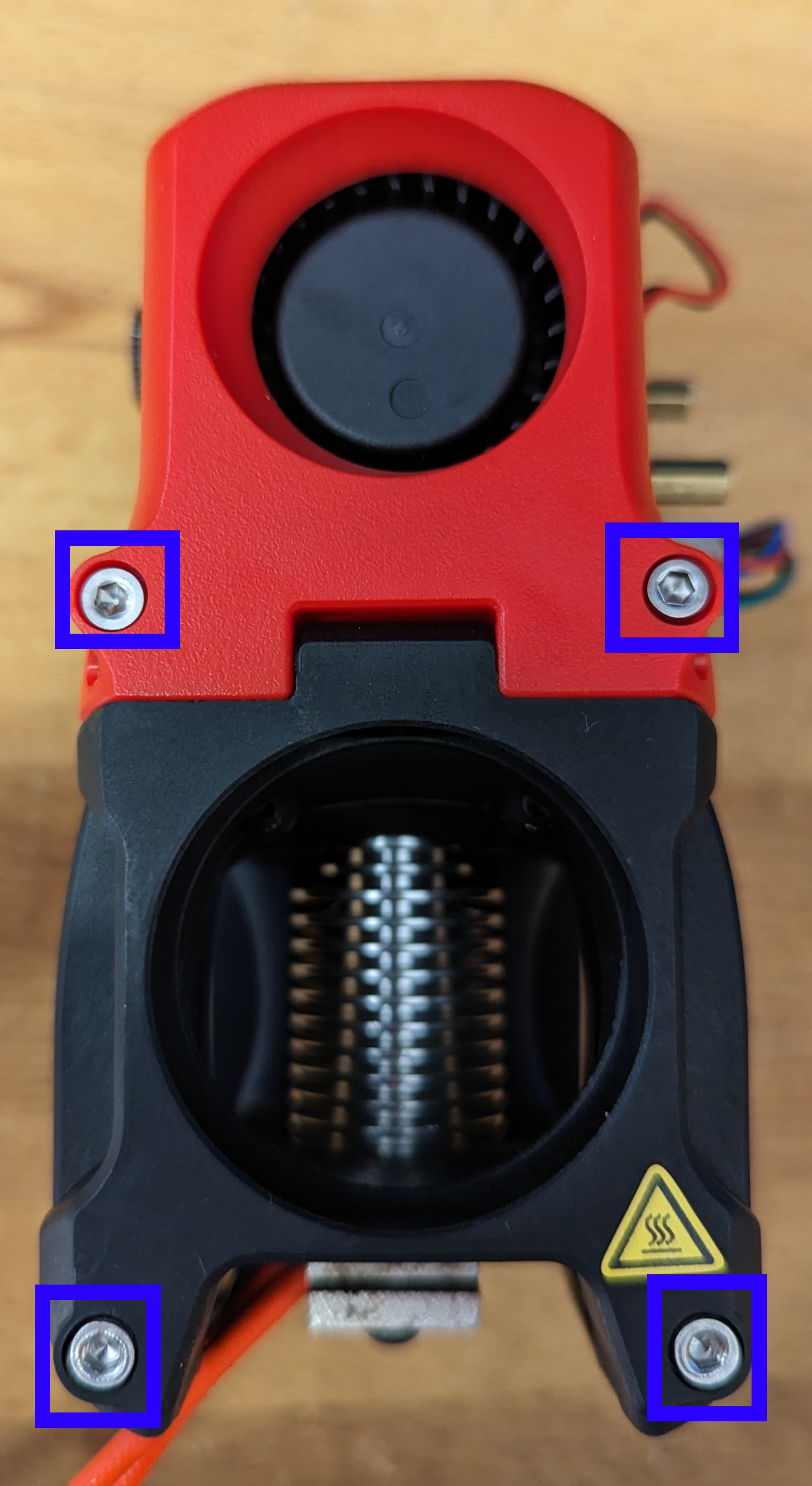
Remove the 2 x M3x12 Screws and 2 x M3x30 Screws securing the fan cover in place. There is no need to unplug the fans but it may make sense to remove the screws just in case they drop out.
Remove the M3x20 securing the latch in place. Remove the latch and place to one side.
Remove the M3x30 securing the guider in place. Remove the guider and place to one side.
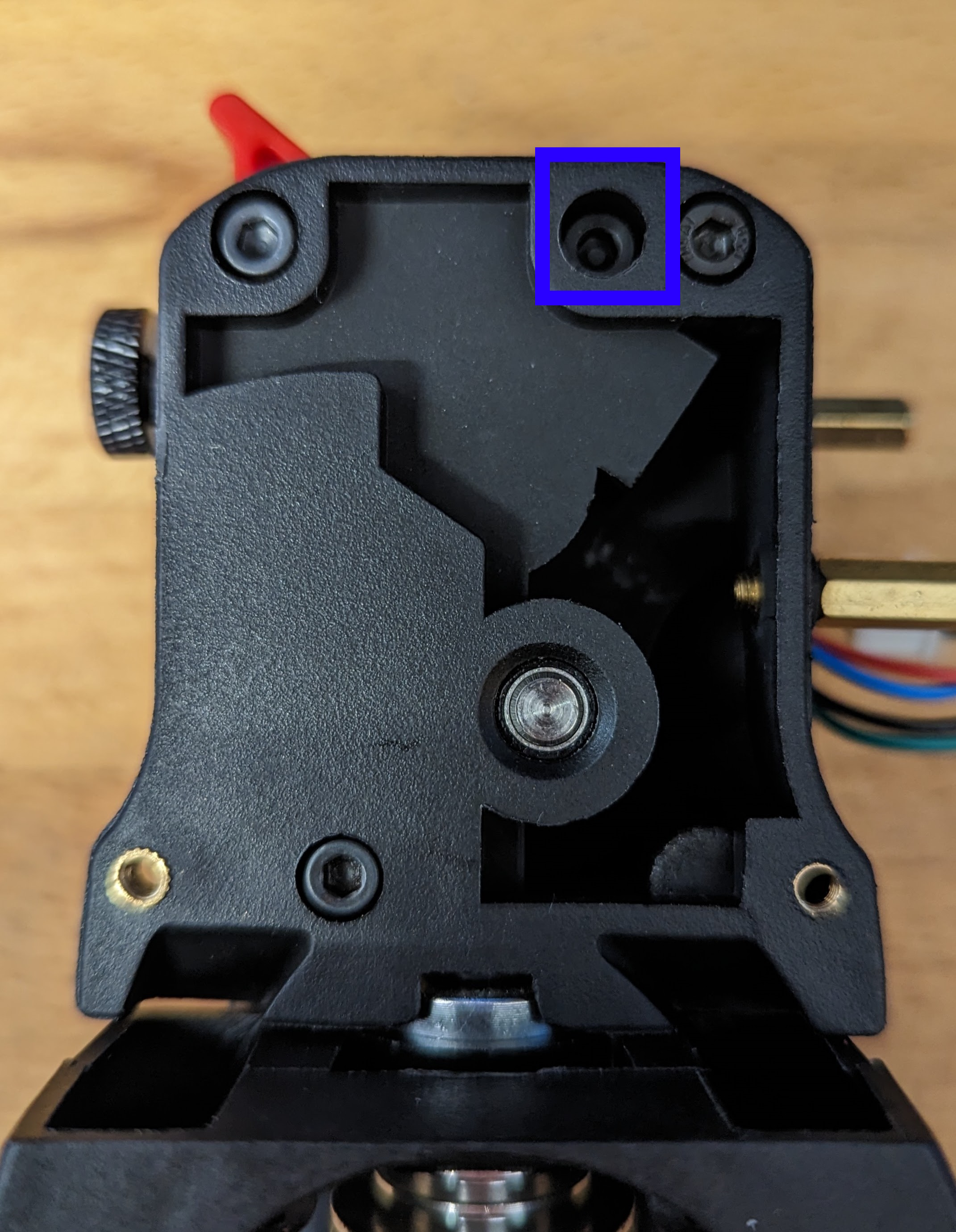
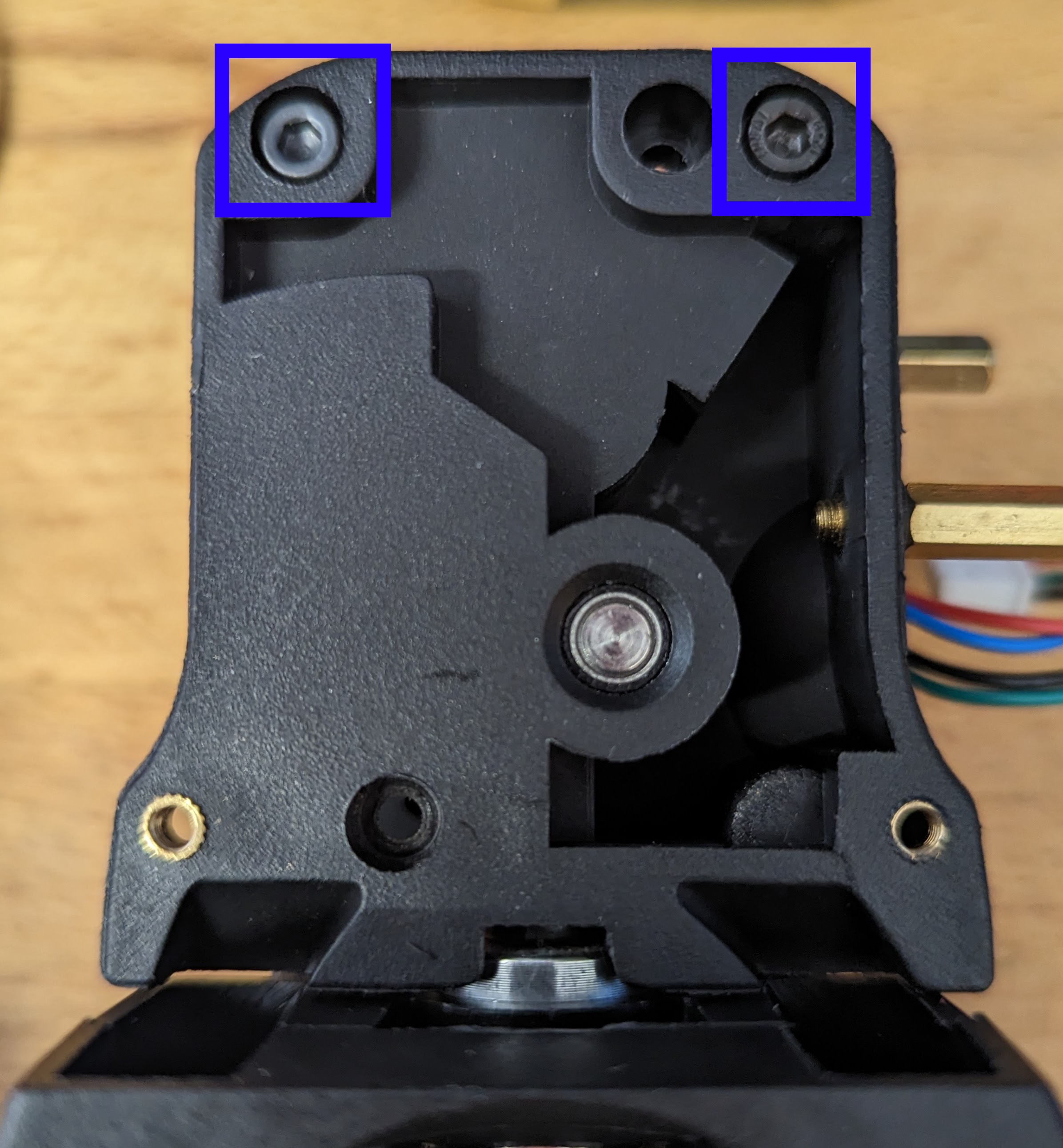
Remove the 2 x M3x30 securing the main body in place. Remove the main body and the drive gear. The MR85 from the motor plate may come away with the drive shaft (which is fine).
Bearing Replacement
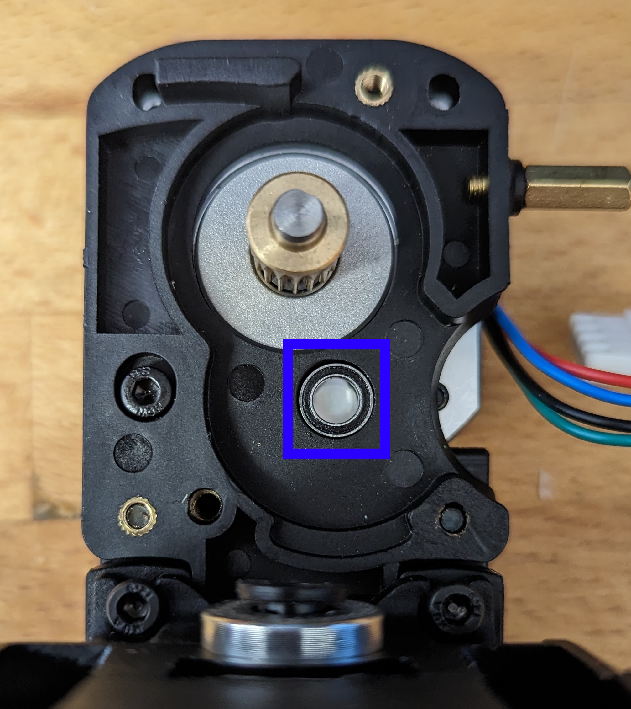
Remove and discard the MR85 from the motor plate. Install the new MR85-ZZ replacement bearing.
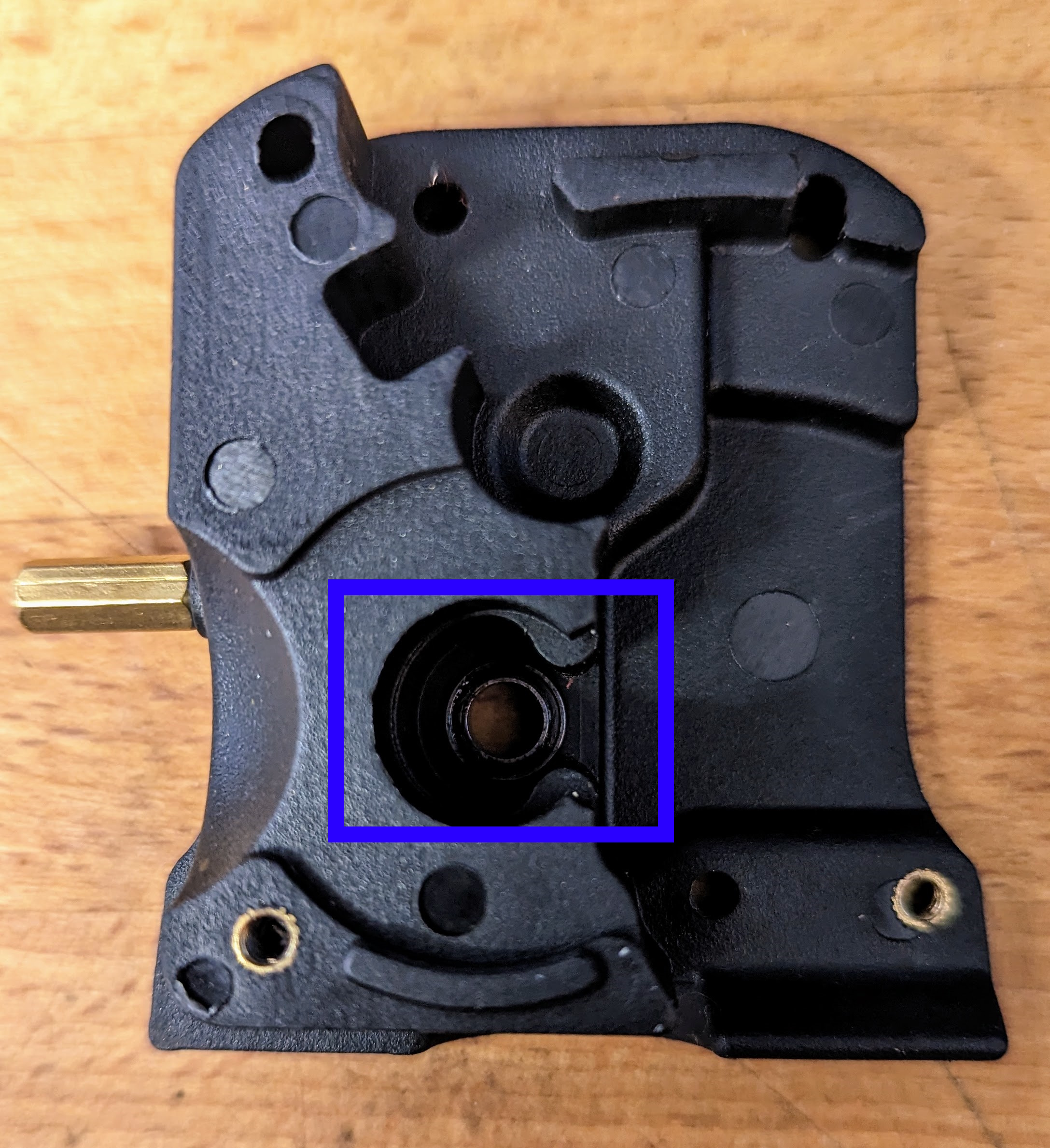
Remove and discard the MR85 from the main body. To do so, turn the main body over and gently tap the bearing from behind. Install the new MR85-ZZ replacement bearing.
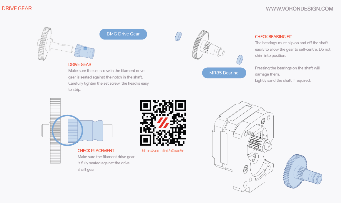
Check the Grubscrew
There have been a number of reports of the drive gear being loose on the drive shaft and now is a perfect time to secure it in place.
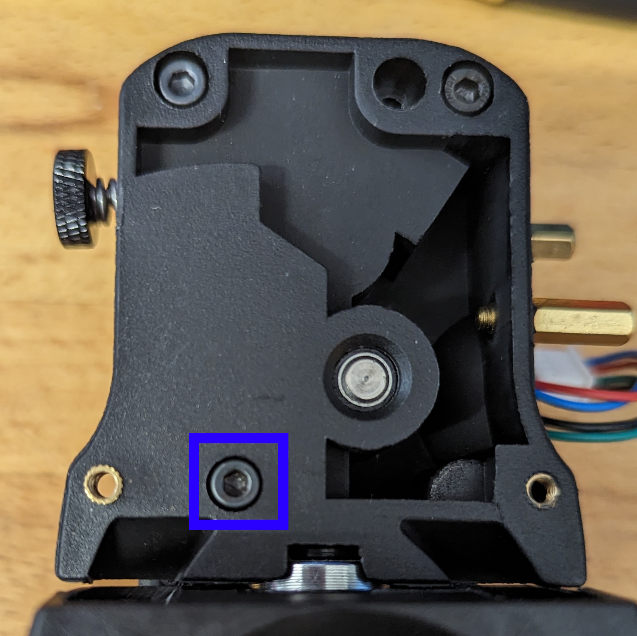
Remove the grubscrew securing the drive gear in place.
Clean it with a cloth and apply a small amount of high strength locking fluid.
Install the grubscrew and secure the drive gear in the position shown below. Be careful when doing so as the head of the grubscrew is easily stripped.
Assembly
Assemble in the reverse order from above. The Voron v2.4r2 assembly manual (from page 160 onwards) can be referenced if required.