Overview
The information here is aimed at connecting a stock ender 3 12864 display but it can also be applied to other 12864 displays (as long as they are ST7567 or ST7920 based).
Ender 3 Stock Display Wiring
The ender 3 stock display can be connected directly to the EXP header of the Fly-E3-Pro. No modifications are required.
Board.txt modifications
The following lines should be added to the board.txt file. If you do not have a board.txt file in sys (the same location as config.g), create one using DWC.
lcd.encoderPinA=LCD_D4
lcd.encoderPinB=LCD_EN
lcd.encoderPinSw=BTN_ENC
lcd.lcdCSPin=LCD_D6
lcd.spiChannel=4
lcd.lcdBeepPin = BEEP
Config.g changes
Add the following line to the end of your config.g
M918 P1 E4 F1000000
Ender 3 Stock Display Wiring With Adapter
The Fly-E3-Pro can have issues with artifcats being displayed on the screen after using it for a while. If this is the case, the Fly-E3-Pro ships with an adapter board and this should be added to the cabling between the screen and the board.
Board.txt modifications
The following lines should be added to the board.txt file.
lcd.encoderPinA=LCD_D6
lcd.encoderPinB=LCD_D5
lcd.encoderPinSw=LCD_D7
lcd.lcdCSPin=LCD_D4
lcd.spiChannel=4
SPI4.pins={LCD_EN, NoPin, BTN_ENC}
lcd.lcdBeepPin = BEEP
Config.g changes
Add the following line to the end of your config.g
M918 P1 E4 F100000
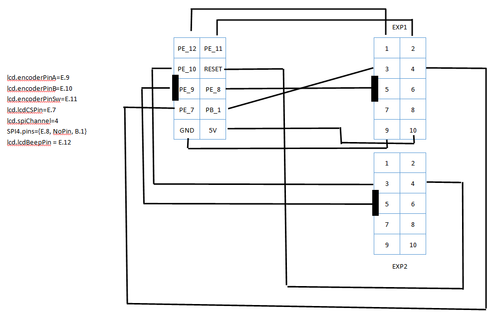
RepRapDiscount Display Wiring
The RepRapDiscount Full Graphic Smart Controller can be connected directly to the EXP header of the Fly-E3-Pro using custom wiring.
Use the image below as a guide. Thanks @Samsan
Board.txt modifications
The following lines should be added to the board.txt file. If you do not have a board.txt file in sys (the same location as config.g), create one using DWC.
lcd.encoderPinA=LCD_D4
lcd.encoderPinB=LCD_EN
lcd.encoderPinSw=BTN_ENC
lcd.lcdCSPin=LCD_D6
lcd.spiChannel=4
lcd.lcdBeepPin = BEEP
Config.g changes
Add the following line to the end of your config.g
M918 P1 E4 F1000000
Fysetc v2.1 Wiring
The Fysetc Mini12864 RGB Panel v2.1 can be connected directly to the EXP header of the Fly-E3-Pro using custom wiring.
Use the image below as a guide. Thanks @Denise_Wink
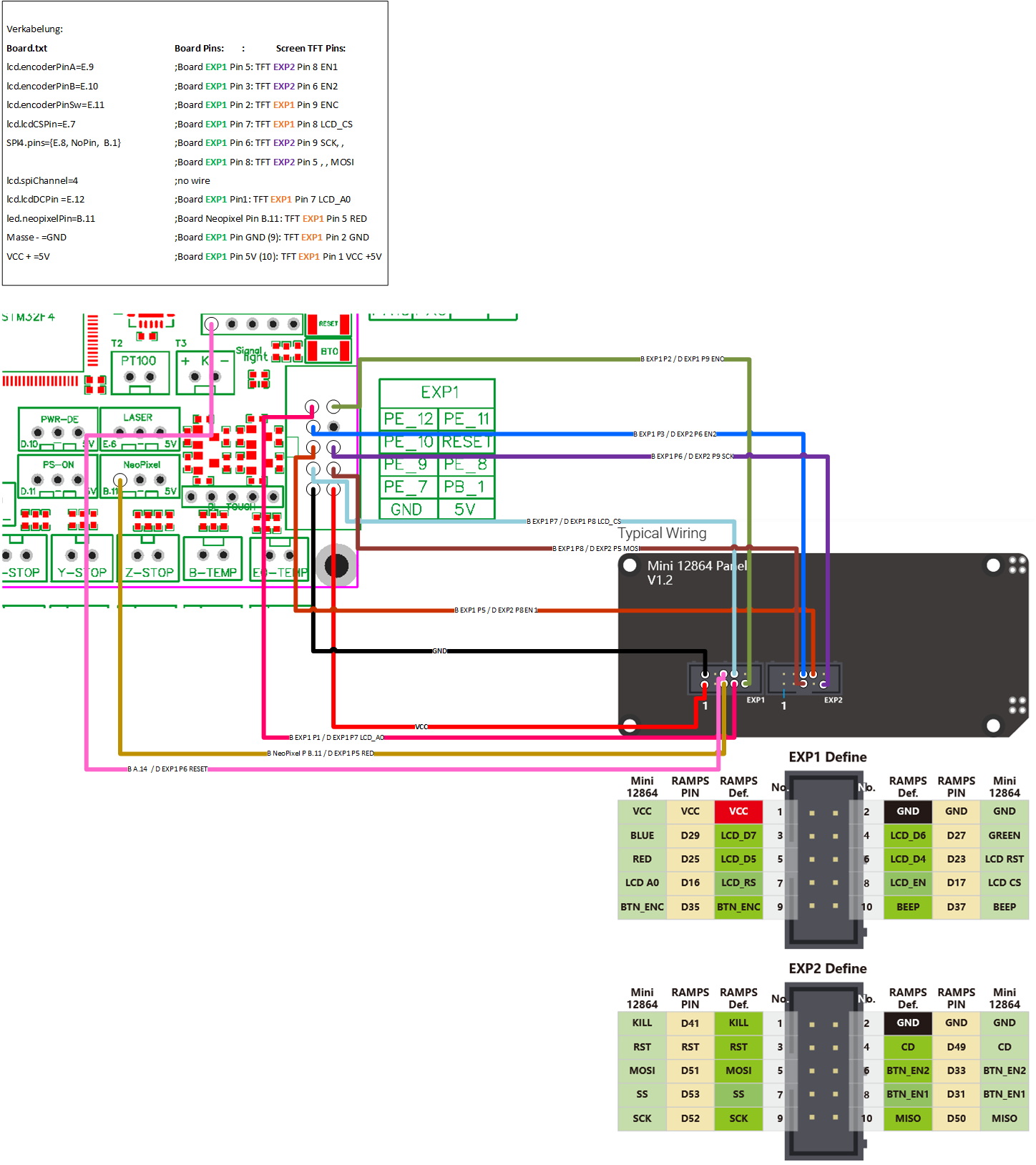
| Pin Number | E3 Pro Pin Location | TFT Pin Location |
|---|---|---|
| lcd.encoderPinA=PE_9 | EXP1 Pin 5 | EXP2 Pin 8 EN1 |
| lcd.encoderPinB=PE_10 | EXP1 Pin 3 | EXP2 Pin 6 EN2 |
| lcd.encoderPinSw=PE_11 | EXP1 Pin 2 | EXP1 Pin 9 ENC |
| lcd.lcdCSPin=PE_7 | EXP1 Pin 7 | EXP1 Pin 8 LCD_CS |
| SPI4.pins={PE_8, NoPin, PB_1} | EXP1 Pin 6, , EXP1 Pin 8 | EXP2 Pin 9 SCK, , EXP2 Pin 5 MOSI |
| lcd.lcdDCPin =PE_12 | EXP1 Pin 1 | EXP1 Pin 7 LCD_A0 |
| led.neopixelPin=PB_11 | Neopixel Pin PB_11 | EXP1 Pin 5 RED |
| Ground | EXP1 Pin GND (9) | EXP1 Pin 2 GND |
| +5v | EXP1 Pin 5V (10) | EXP1 Pin 1 VCC +5V |
| LCD Reset | SWCLK on STLink Pin PA_14 | EXP1 Pin 6 LCD RST |
ST7567 Board.txt modifications
The following lines should be added to the board.txt file.
lcd.encoderPinA=PE_9
lcd.encoderPinB=PE_10
lcd.encoderPinSw=PE_11
lcd.lcdCSPin=PE_7
SPI4.pins={PE_8, NoPin, PB_1}
lcd.spiChannel=4
lcd.lcdDCPin = PE_12
led.neopixelPin=PB_11
ST7567 Config.g changes
Add the following line to the end of your config.g
M98 P"screen.g"
Add a file in your sys folder called screen.g and add the following contents
; ST7567 Init for FYSETC Mini12864 Panel V2.1
; Turn off backlight
m150 X2 R0 U0 B0 S3 F0
; Configure reset pin
M950 P1 C"PA_14"
; hardware reset of LCD
M42 P1 S0
G4 P500
M42 P1 S1
; Turn display on
M918 P2 C30 F1000000 E4
; Fade in backlight
while iterations < 256
 m150 X2 R255 U255 B255 P{iterations} S1 F0
 G4 P20
; flash Button 3 times
while iterations < 3
 m150 X2 R255 U255 B255 P255 S1 F1
 m150 X2 R0 U255 B0 P255 S2 F0
 G4 P250
 m150 X2 R255 U255 B255 P255 S1 F1
 m150 X2 R0 U255 B0 P0 S2 F0
 G4 P250
; Display "ready" button state
m150 X2 R255 U255 B255 P255 S1 F1
m150 X2 R255 U0 B0 P255 S2 F0
Menu Files
Menu files must be uploaded to allow the display to generate the correct information. This can be done in two ways. First, obtain the recommended menu files from here
Method 1 - WiFi Mode only
Extract the contents of the zip file you downloaded above and place them in a folder called “Menu” on the SD card of the Fly-E3-Pro.
Method 2
Activate the display using the config.g changes above.
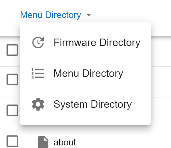
On the “System” tab, above the list of files, is a dropdown menu that defaults to “System Directory”. Select this and change it to “Menu Directory”.
Then upload the menu zip file.
Troubleshooting
If the screen is showing artifacts/random characters on the screen, the following may improve/eliminate the issue
- Lower the SPI frequency by half. This is the F value in M918.
- Reduce the length of the cable between the screen and the board.
- Ensure that the cable between the screen and the board is routed away from other cables, especially motor cables.
- Add a ferrite ring to the cable between the screen and the board.