Overview
The SKR 1.4 is an LPC1768 based board and the v1.4T is an LPC1769 based board. They have the same pinout etc, only the MCU (micro controller unit) is different. All tasks are applicable to both the SKR v1.4 and SKR v1.4T.
There are a number of steps that can be done to limit this issue.
1. Keep the wires between the controller and the Pi short
2. Use either a ribbon cable, or if using jumper wires then use ribbon-style jumper wire strips with the individual conductors separate only at the ends
3. Use multiple ground connections between the two
4. Beware of ground loops. Problems are likely if more than one of the the PSU supplying the controller, the PSU supplying the Pi, and any other equipment that the Pi is connected to (other than via Ethernet) has its signal ground connected to the mains ground in the 3-pin plug that supplies the power. RPi PSUs are usually not grounded. ATX PSUs always are. Meanwell-style PSUs have a ground connection, but it is up to you whether you link mains ground to PSU negative output.
In short, these disconnects may happen to you or they may not. If they happen and you are unable to fix them, then the only remaining options are track down the noise by changing components one by one or switch to using WiFi rather than an SBC.
Firmware File
Choose the correct corresponding firmware (firmware-lpc-sbc.bin) from here. Remember to rename it to firmware.bin. Put it in the root of a FAT32 formatted SD card.
SBC
Connecting a Single Board Computer, such as a raspberry pi 3B/3B+/4.
Prepare the Raspberry Pi
Follow the instructions detailed here.
BOM
- 5 x 100R resistor
- jumpers or other ways of connecting to the SKR
Connecting the SBC to the SKR v1.4 and v1.4T
The pinout for the SKR can be found here and the schematic for the Duet 3 for reference can be found here. The raspberry pi GPIO pinout can be found here.
The table below shows the pins required on the SBC and what they are connected to on the SKR. Please ensure that your cables are no longer than 30cm although they should ideally be as short as possible.
| SBC Pin | SKR Pin | Resistor Value |
|---|---|---|
| 23/BCM11/SPI0 Clk | 0.15 on EXP2 | 100R |
| 21/BCM9/SPI0 Miso | 0.17 on EXP2 | 100R |
| 19/BCM10/SPI0 Mosi | 0.18 on EXP2 | 100R |
| 24/BCM8/SPIO CE0 | 0.16 on EXP2 | 100R |
| 22/BCM25 | 1.31 on EXP2 | 100R |
| 20/GND | GND on EXP2 | None |
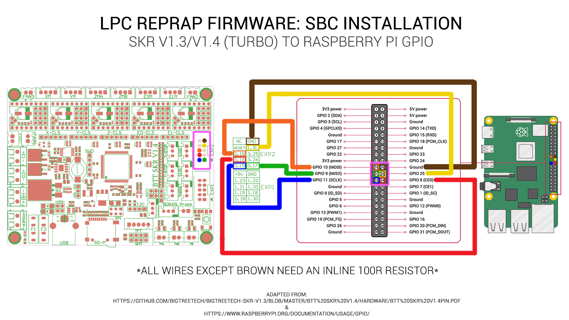
Image created by teaching tech
Don’t power the raspberry pi from the SKR. Either us a 12/24v to 5v step down transformer or power the pi from the micro usb or usb-c port.
Prepare the SD Card
All the SD card on the SKR v1.4 needs is the board.txt file with the following contents.
//Config for BIQU SKR v1.4
board = biquskr_1.4
sbc.TfrReadyPin = 1.31
heat.tempSensePins = { 0.25, 0.24, 0.23 }
If using TMC22XX drivers (thats either the TMC2208, TMC2209, TMC2225 or TMC2226), the following line must also be added to the board.txt file
stepper.numSmartDrivers = X
Where X is the number of drivers fitted. The drivers must be continuous and start at unit 0. So, for the SKR board, if you have say 3 TMC2208s and 1 other driver, the 2208s must be in slots 0, 1, 2 and the remaining driver in slot 3 or 4. You can use RRF to assign any of those slots to an axis/extruder.
Sensorless Homing
If using sensorless homing/stall detection (supported by only the TMC2209 or TMC2226), the following line must be added to the board.txt file.
stepper.TmcDiagPins = {1.29, 1.28, 1.27, 1.26, 1.25}
Please only include the diag pin numbers where you intend to use sensorless homing on that axis. For example, if you only intend to use sensorless homing/stall detection on driver 0 and driver 1, only include 1.29 and 1.28 in your board.txt file.
For more information about setting up sensorless homing, please read this.
Driver Diag Pin
The driver diag pin is used for sensorless homing and stall detection.
The SKR v1.4 does not have a way of disabling the diag pin.
If you plan on using endstops rather than sensorless homing, you need to bend or remove the diag pin.
Board.txt Location
Place the board.txt file in a directory called “sys” on the SD card and install the SD card in the SKR v1.4.
Finally…
Turn it all on and you should be good to go.
You can either navigate to duet3.local or find the IP address of the rasberry pi using your router. If you don’t have access to that, use something like Fing to scan your network.
Once you’ve connected to the raspberry pi through your router, start to customise your config.g file etc or upload the outputted zip file from the Configurator to the pi using the system tab of DWC.
Errors
Please report any disconnects on either the forum or discord.
Changing the SBC hostname
This is an optional step if you only have a single duet3 on your network. It is required if you have more than one SBC configured RRF setup (as each setup on a network needs a unique host name) or you just want to change the name from the default “duet3”.
The name of the printer is its hostname on the network, you will need to connect to the SBC over SSH in order to run the Raspberry Pi configuration utility and change the hostname.
- Connect via ssh
- At a command prompt type
sudo raspi-config -
Select “System Options” -> Hostname-> “OK”-> and set the new printername/hostname.
- Select “Finish” and reboot.
Once up and running
You will need to PID tune your tools and your bed. Please be aware that bed tuning may take up to an hour and tool tuning normally takes around 15 minutes. If it takes longer, that is also fine as up to 30 cycles may be ran.
To tune the bed, run the following command, changing the temperature (the S value) if a different tuning temperature is required.
M303 H0 S60
To tune each tool, run the following command, changing the temperature (the S value) if a different tuning temperature is required. This proceedure will activate the part cooling fans during the final phase of the tuning process so their effect is taken into account. If your printer has more than one tool, make sure each one of them is tuned.
M303 T0 S220
Once the tuning is complete, either copy the M307 command into the heater definitions or send M500, ensuring you have M501 at the end of your config.g.
If the tuning fails at the end, carry on saving the values as in most cases the outputted values still work correctly.
If the values still result in a heater fault, please refer to this wiki page for information about how to adjust the values manually.