Overview
The below describes an alternative method of connecting an ESP32 to the Fly-407ZG. This alternative modification provides 2 advantages.
- SPI controlled drivers (TMC5160) can be used
- Both RRF updating of the ESP32 and serial displays can be used at the same time
This will involve soldering some cables to the board.
BOM
- 1 x ESP32 adapter (information available here will be suitable)
- Some cable
Connecting the Adapter
This example uses the Fly WiFi Adapter.
Cables to solder to the Fly-407ZG
11 cables are to be soldered to the board. 6 of these are on the onboard ESP pads, 3 to the eeprom and MAX6675 connections and 2 to EXP1.
Connect the 6 cables to the Fly-407ZG as shown below
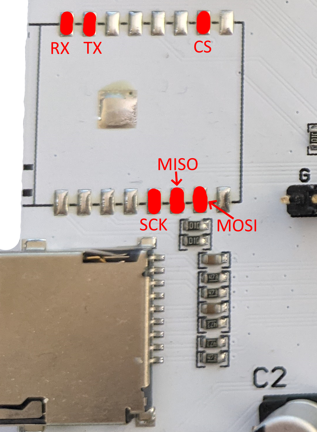
Connect the 3 cables to the Fly-407ZG as shown below
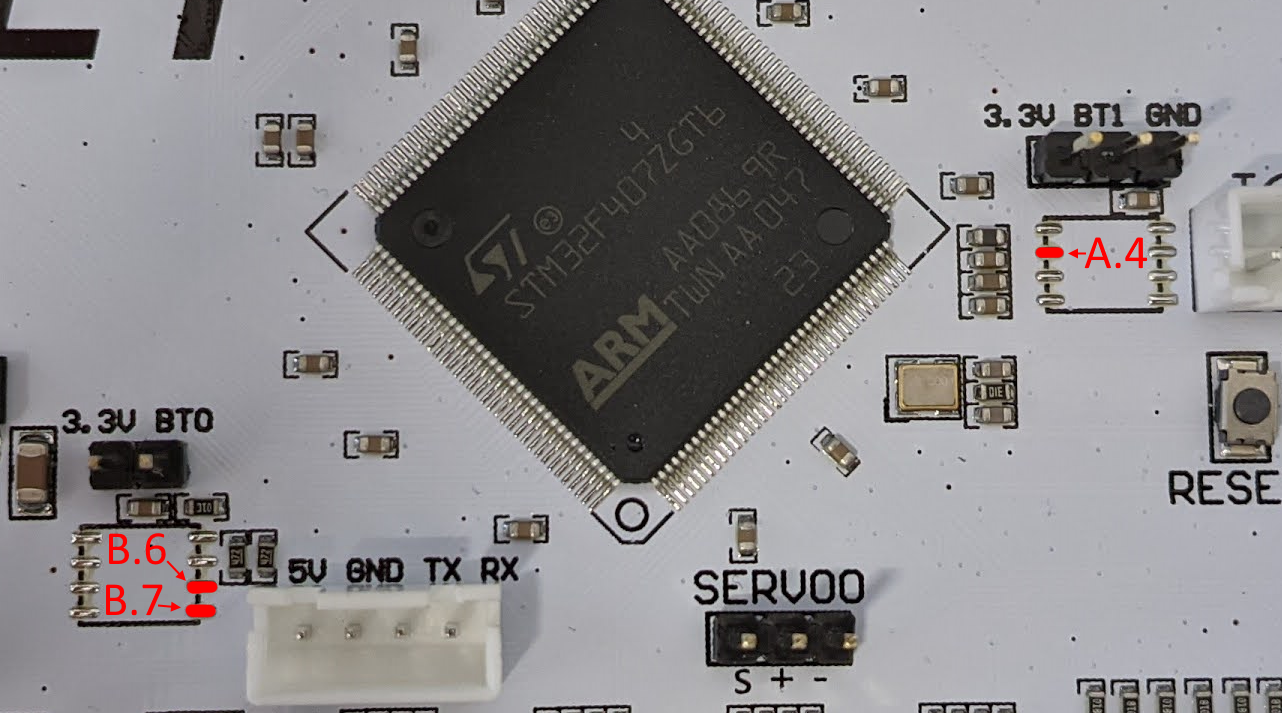
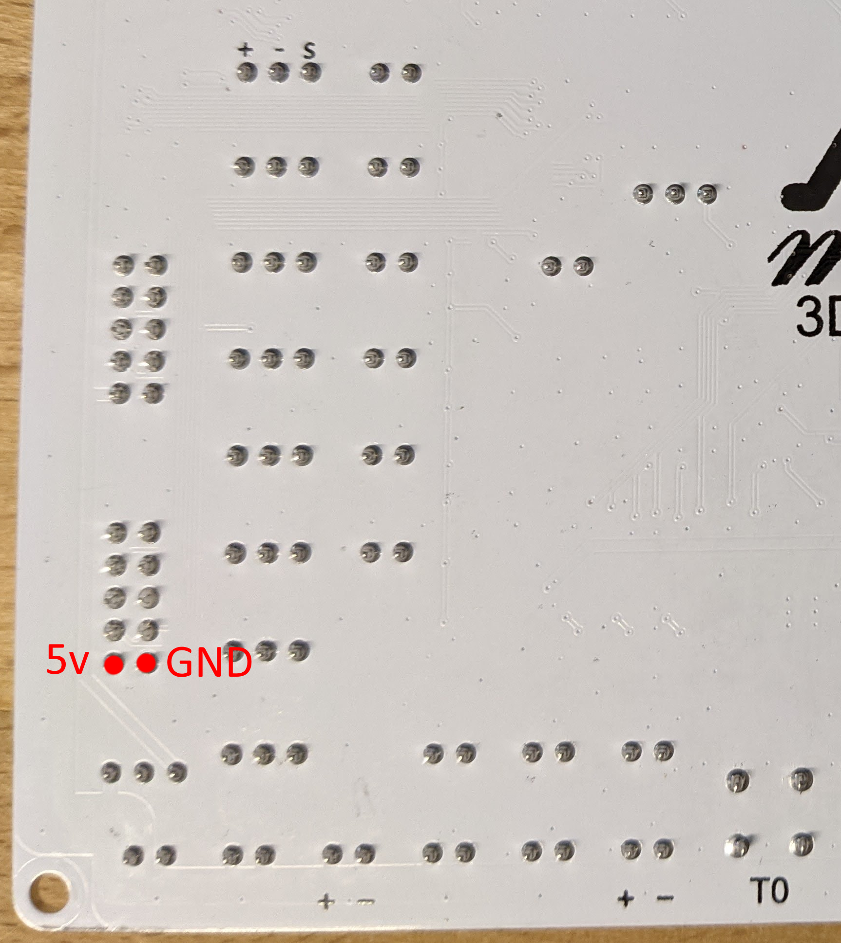
Connect the 2 cables to the Fly-407ZG as shown below
Cables to solder to the Adapter
The 11 cables soldered to the Fly-407ZG then need to be attached to the adapter.
2 of the 11 cables should be attached as shown below. The RX cable from the Fly-407ZG should be connected to the TX pad on the adapter and the TX cable from the Fly-407ZG should be connected to the RX pad on the adapter.
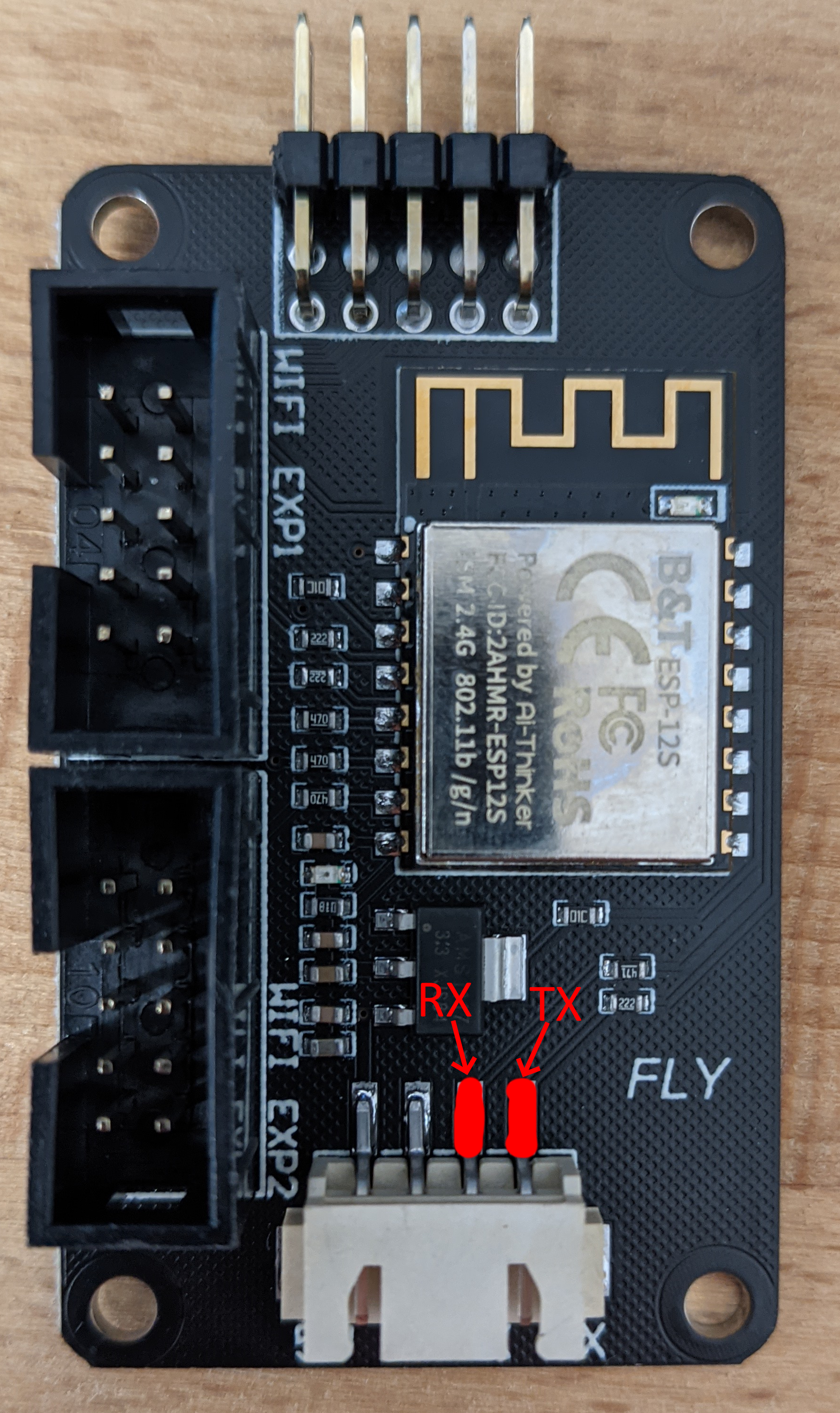
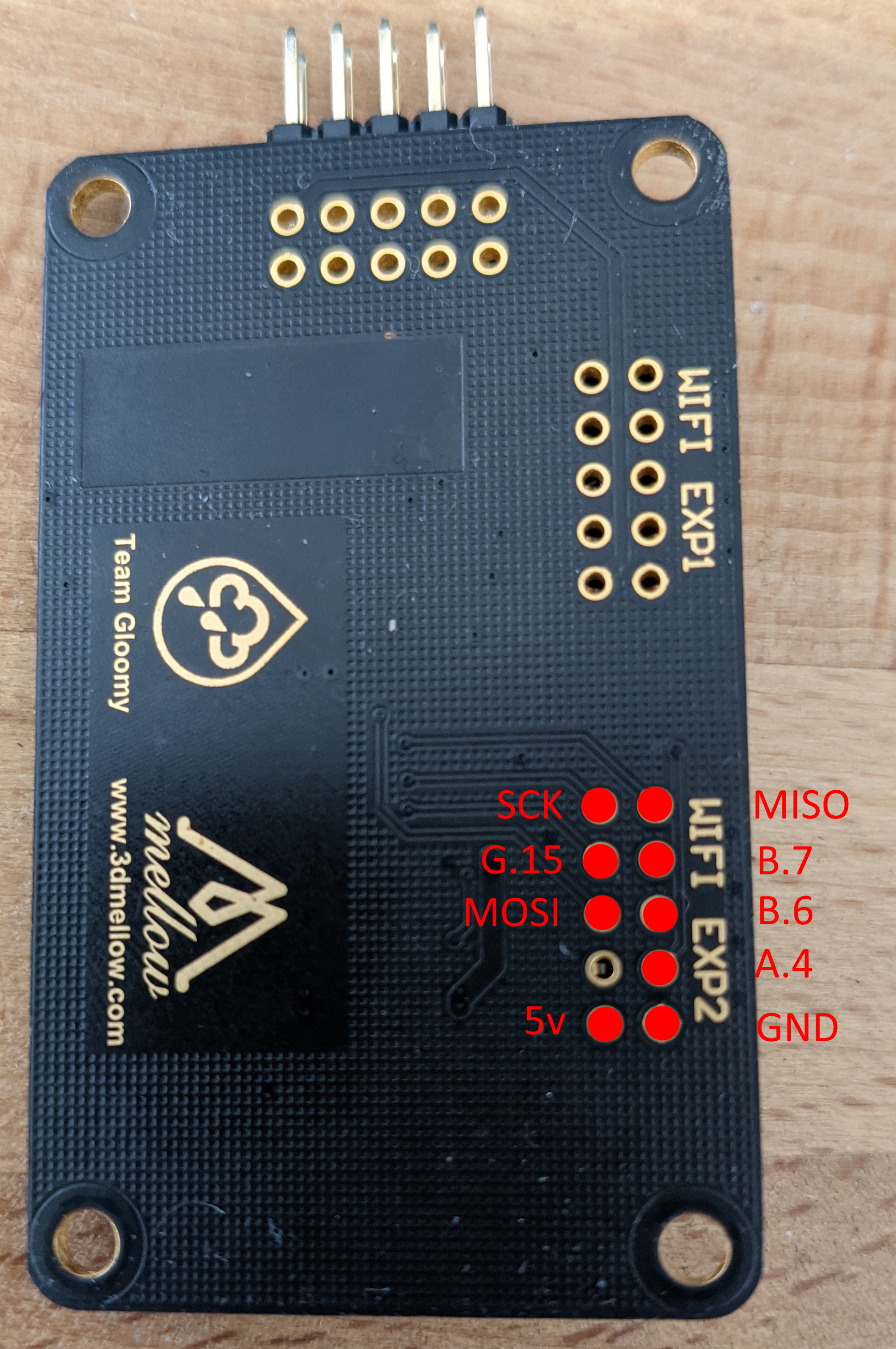
The remainder of the cables are to be connected to the adapter as shown below.
Board.txt Changes
The following changes should be made to the board.txt file
//ESP32 Settings
SPI2.pins={ PB_3, PB_4, PB_5 }
8266wifi.espDataReadyPin = PB_7
8266wifi.lpcTfrReadyPin = PB_6
8266wifi.espResetPin = PA_4
8266wifi.csPin = PG_15
8266wifi.spiChannel=2
serial.aux.rxTxPins = { PA_10, PA_9 }
8266wifi.serialRxTxPins = { PG_9, PG_14 }
</div>
</div>