Overview
The Fly-SB2040 Max V3 Toolboard can be connected to any of the mainboards produced by Duet3D, an STM32H723, STM32H743 or an STM32F4 with an spican module.
Preparation
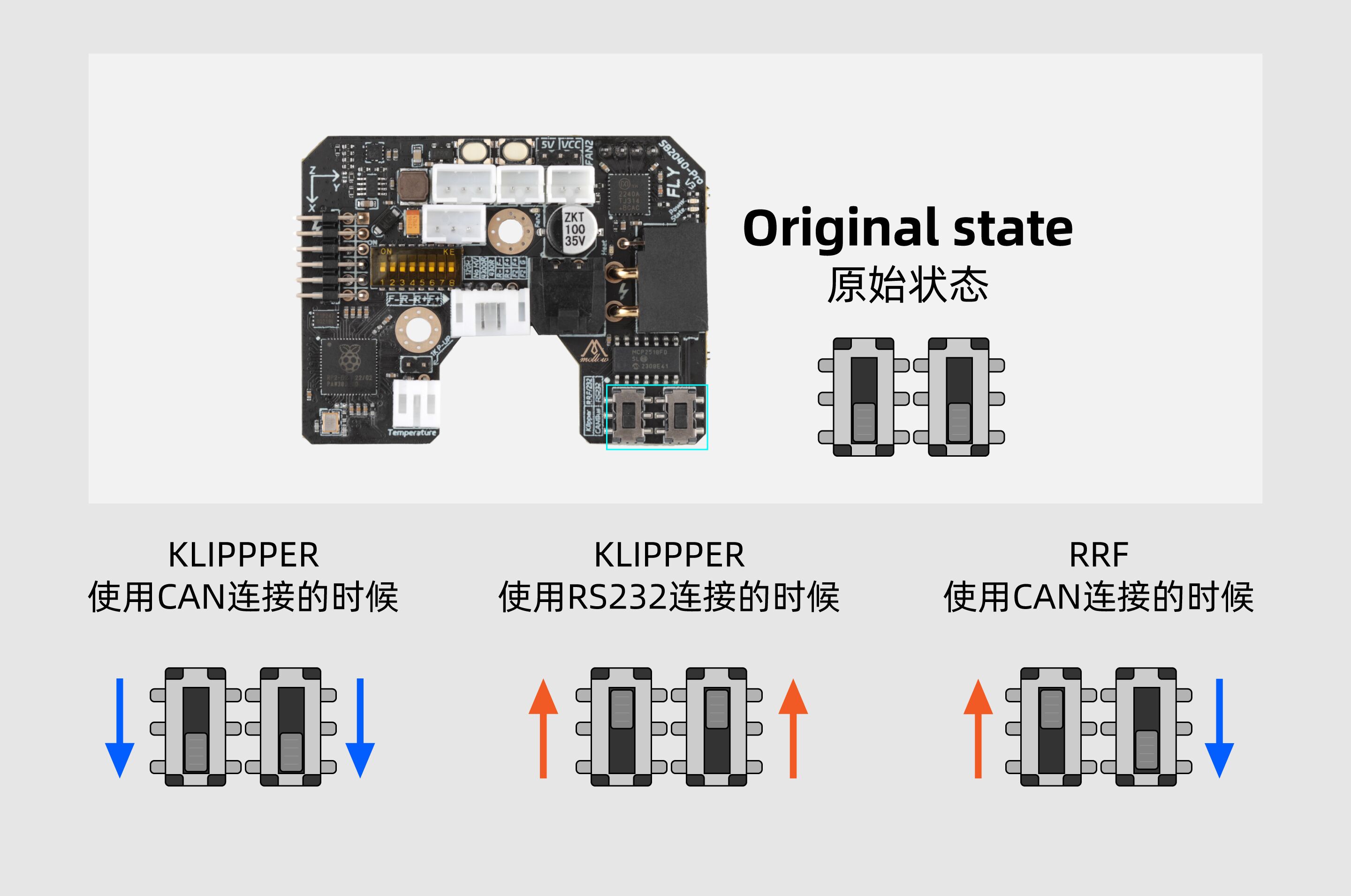
You need to make sure the CAN communication switches are in the correct orientation for RRF as shown below.
How to connect the board
CAN-FD only requires 2 wires to be connected between each board, CAN-H and CAN-L.
The Fly-SB2040 Max V3 is supplied with a ~3m long cable that has both power and CAN cables.
Connect the power cables to your 12/24v PSU.
The Yellow cable is CAN-H and the White cable is CAN-L. The Yellow cable should be connected to the CAN-H connection on the mainboard or spican module and the white cable connected to the CAN-L connection on the mainboard or spican module.
Commissioning
All boards in the system must have different CAN addresses. Fly-RRF36 Toolboards are by default set to a CAN address of 124. Therefore, if you have more than one new Toolboard, only one of them must be powered up and connected to the CAN bus at a time until you have changed the default CAN address. So disconnect power to all but one of them (you can leave the CAN bus connected if it’s easier).
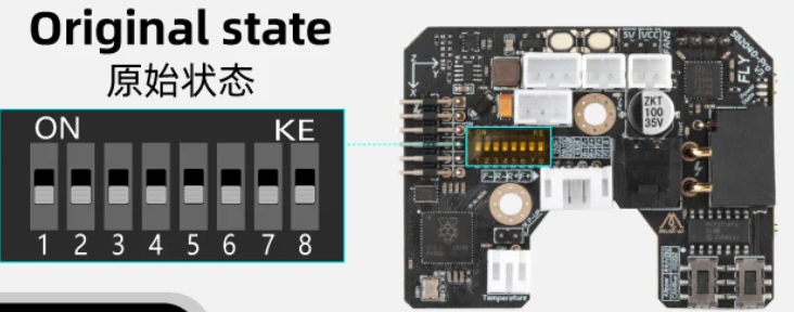
If the Fly-SB2040 Max V3 is the last board on the CANbus then it requires the 120ohm resistor enabling. To do so, set DIP switch 1 to ON.
Checking the toolboard connection is functional
Power up the printer. The 3.3v, 12v and Power LEDs on the toolboard should illuminate. The “working” LED near the RP2040 MCU will blink rapidly for a few seconds until a connection is established. The LED will then blink roughly once every second.
You can then check that the toolboard is communicating correctly by sending the following command:
M115 B124
The firmware version running on the toolboard will then be reported.
Set the CAN address
- Send command M115 B# to verify that the main board can communicate with the Toolboard, where # is the original CAN address (normally 124)
- Send command M952 B# A## where ## is the new address you want to use. We suggest you use addresses starting at 20 for Toolboards. So for the first Toolboard, if your new CAN board was at address 124, send M952 B124 A20.
- Power the system down and up again, or send M999 B124. This will cause the Toolboard to restart with the new address.
- Send command M115 B20 (or whatever address you chose) to verify that you can communicate with the Toolboard at its new address
- You can now power up the next Toolboard and commission it in the same way, choosing a different CAN address for it.
Startup Time
It is recommended to add the following to config.g, before any commands that reference any CAN bus connected expansion boards
G4 S2 ; wait for expansion boards to start