Overview
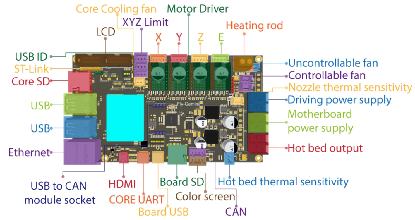
The Fly-Gemini-V1 STM32F405VGT6 based board with an Allwinner H5 built in for SBC functionality.
Two SD cards are required when using this board. One for the STM32 side and one for the SBC side.
Board Setup
Jumper Setup
There are two rows of DIP switches that require setting correctly for RRF operation.
Row 1
Row 1 is the row of DIP switches nearest the USB ports.
If you want to be able to access the STM32 chip from the “Board USB” port, then ensure that switches 1 to 6 are in the off position and 7 to 8 are in the on position.
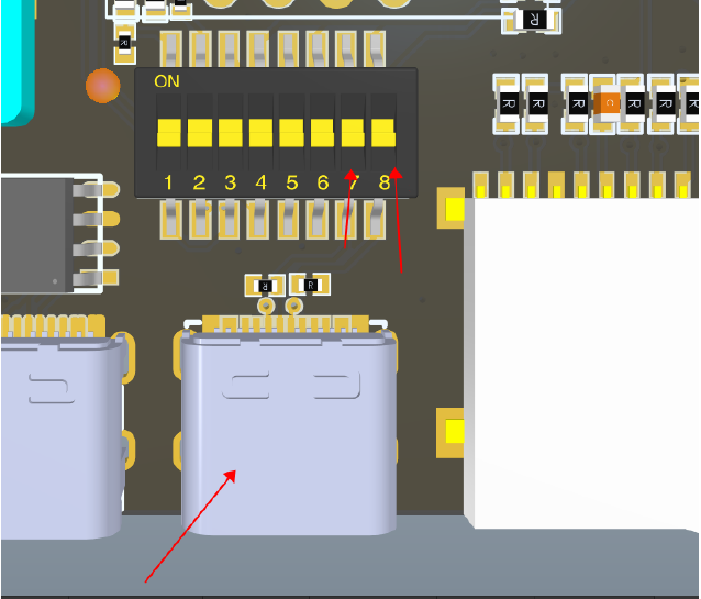
If you want to be able to acces the STM32 chip from picocom (installed by default) ran from the SBC, then ensure that switches 1 and 2 are in the off position, 3 and 4 in the on position and 5 to 8 are in the off poition.
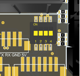
Row 2
On the row near the EXP headers, ensure that switches 1 to 4 are in the on position.
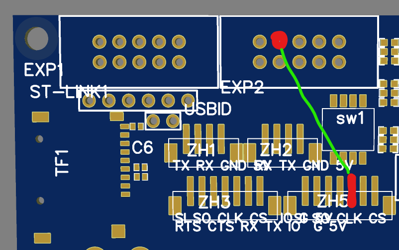
Additional Cable
An additional cable requires adding to allow the connection between the STM32 and the SBC to function correctly.
It should be added as shown below between the 3rd from the right pin of the small 7 pin connector to the left of the Core-Fan header and the second pin from the left on the top row of EXP2 (PPB_3).
STM32 Setup
Firmware File
Choose the correct corresponding firmware (firmware-stm32f4-sbc.bin) from here. Remember to rename it to firmware.bin. Put it in the root of a small FAT32 formatted SD card. This will be placed in the STM32 side of the board. The maximum size supported card is 32GB.
Board.txt
The SD card on the Fly-Gemini-V1 also needs a board.txt file with the following contents.
//Config for Fly-Gemini-V1
board = fly_gemini
sbc.TfrReadyPin = PB_3
Drivers
Although the original method of having the firmware detect the drivers is still supported, as we have now added TMC2240 support, there is now a new method.
The following line should be added (obviously with the array entries matching your drivers and their locations):
stepper.numSmartDrivers = X
stepper.DriverType = {Tmc2208, Tmc2240, tmc2209, tmc5160, stepdir}
For the number of smart drivers, if you have the following installed (tmc2209, none, tm5160, stepdir, tmc2209) then numSmartDrivers needs to be set to 5 not to 3. Basically it means how many entries there are in the driver types array. Entries after that number get set to stepdir.
The DriverType array allows for any driver to be used in any slot so there is no order requirement like the previous detection method. The array must also include an entry for each driver slot up to the last one thats populated.
The following list of entries are valid:
none
stepdir
tmc2208
tmc2209
tmc2660
tmc5160
tmc2240
If using TMC2240 or TMC5160 drivers, you also need to add the correct spi channel:
stepper.spiChannel =
SPI.pins =
TMC2240 Driver Temperature
TMC2240 drivers support reporting their own temperature, rather than just hot and very hot like the other TMC drivers. To utilise this, add the following line to your config.g
M308 S11 Y"drivers"
This will return the highest temperature reading from any of the drivers, 2240s will return the actual temperature, other drivers will return 0, 100 or 150 (as before).
If you want to know the temperature of a particular driver you need to add the following line (as well as the above):
M308 S12 Y"drivertemp" p"S11.X"
Where x is the driver number that matches the driver number used by M569
Sensorless Homing
Follow the instructions as found here
Smart Drivers
If using TMC5160 or TMC22XX drivers (where 22XX is either the TMC2208, TMC2209, TMC2225 or TMC2226), the following line must also be added to the board.txt file
stepper.numSmartDrivers = X
Where X is the number of drivers fitted in total.
TMC5160 SPI Drivers
If using TMC5160 drivers, the following lines must also be added to the board.txt file.
stepper.num5160Drivers = X
stepper.spiChannel =
SPI.pins =
Where X is the number of TMC5160 drivers fitted.
The drivers must be grouped together with the installed TMC5160s first. They can have gaps between each driver and/or driver type. So, if you have say 3 TMC5160s and 1 TMC22XX and 1 other driver, the 5160s should installed first (e.g. in slots 0, 1 and 2 or slots 0, 3 and 4), the TMC22XX in a slot after the 5160 and the remaining driver last. You can use RRF to assign any of those slots to an axis/extruder.
Sensorless Homing
Follow the instructions as found here
Board.txt Location
Place the board.txt file in a directory called “sys” on the SD card and install the SD card in the Fly-Gemini-V1.
SBC Preparation
Download the latest prepared image from here.
The image has DSF installed and ready to go, with the correct transfer pin configured.
Flash the SD Card
Using balenaEtcher, flash the downloaded image to an SD card 8Gb or larger.
Place the SD Card into the Core-SD slot.
Power Up the Board
The board and bed power supply should be 12/24v.
The drivers power supply should be 12/24/48v. 48v should only be used with compatible 48v 5160 drivers.
Turn it all on and you should be good to go.
If using Ethernet, you can either navigate to fly-gemini.local or find the IP address of the rasberry pi using your router. If you don’t have access to that, use something like Fing to scan your network.
SSH into the board
Either via CORE UART USB connection or by using SSH via the network connection.
The default username is root and the default password is 1234. Follow the onscreen instructions and change the root password and setup a new user. I recommend using ZSH rather than bash.
How to connect to wireless
If your SBC has onboard wireless capability or if you use a 3rd party wireless adapter on USB supported by Armbian, you can use nmtui-connect to browse and connect to your WiFi AP.
Finally…
Once you’ve connected to the raspberry pi through your router, start to customise your config.g file etc or upload the outputted zip file from the Configurator to the pi using the system tab of Duet Web Control (DWC).
Remember to PID tune the bed and tool
You will need to PID tune your tools and your bed. Please be aware that bed tuning may take up to an hour and tool tuning normally takes around 15 minutes. If it takes longer, that is also fine as up to 30 cycles may be ran.
To tune the bed, run the following command, changing the temperature (the S value) if a different tuning temperature is required.
M303 H0 S60
To tune each tool, run the following command, changing the temperature (the S value) if a different tuning temperature is required. This proceedure will activate the part cooling fans during the final phase of the tuning process so their effect is taken into account. If your printer has more than one tool, make sure each one of them is tuned.
M303 T0 S220
Once the tuning is complete, either copy the M307 command into the heater definitions or send M500, ensuring you have M501 at the end of your config.g.
If the tuning fails at the end, carry on saving the values as in most cases the outputted values still work correctly.
If the values still result in a heater fault, please refer to this wiki page for information about how to adjust the values manually.