Overview
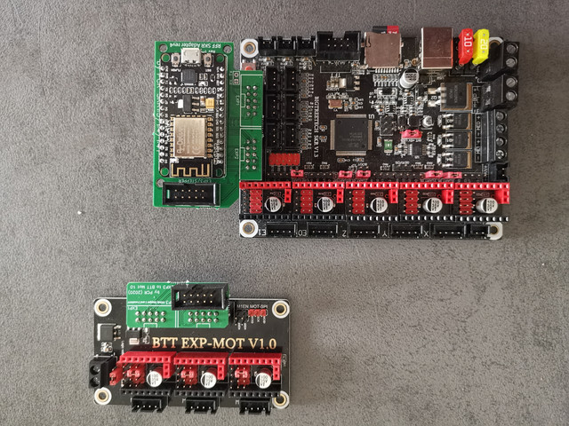
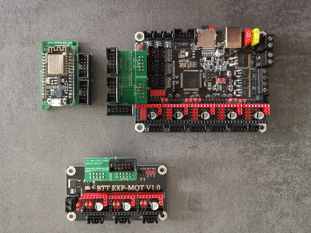
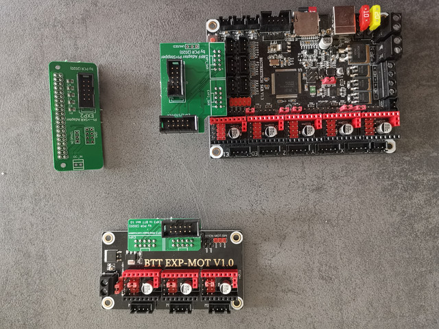
BigTreeTech released the BTT-MOT-EXP. It is an adapter that would ordinarily allow 3 more extra drivers to be added to an SKR Pro v1.2. To allow a WiFi or SBC connection, some of those pins required. Luckily though, TeamGloomy have produced an adapter to allow the BTT-MOT-EXP to be connected and for 2 out of the 3 driver connections to be used.


Connecting the boards
A single 10-pin IDC cable is required between the WiFi/adaptor board and the board connected to the BTT EXP-MOT V1.0.
12/24v power should be connected to the BTT-MOT-EXP to power the drivers.
If using the drivers in UART mode, a jumper should be added to the pins underneath the driver as normal.
SKR Pro v1.2 Board.txt configuration
Please edit the stepper.numSmartDrivers in the board.txt file to 8 (assuming you have TMC2208, TMC2009, TMC2225 or TMC2226 drivers in all other sockets).
stepper.numSmartDrivers = 8
Please add the following lines to the board.txt.
stepper.enablePins = { PF_2, PD_7, PC_0, PC_3, PA_3, PF_0, PD_11, PG_7 }
stepper.stepPins = { PE_9, PE_11, PE_13, PE_14, PD_15, PD_13, PG_3, PG_2 }
stepper.directionPins = { PF_1, PE_8, PC_2, PA_0, PE_7, PG_9, PD_10, PG_6 }
stepper.TmcUartPins = { PC_13, PE_3, PE_1, PD_4, PD_1, PD_6, PF_11, PG_10 }
Config.g Modification
The two added drivers would become driver 6 and driver 7.
e.g.
M569 P6 S0
M569 P7 S0