The pin names of the GTR + M5 in the firmware
Warning: The GTR sensorless homing jumpers don’t do anything so if you don’t want to use sensorless homing and use normal endstops, you will have to remove the diag pin from your drivers - Evidence
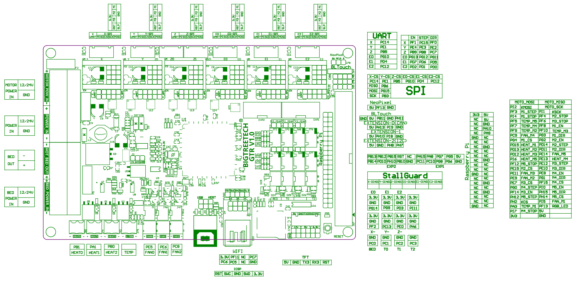
GTR Pinout Diagram
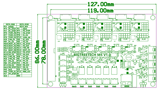
M5 Pinout Diagram
GTR + M5 Driver Pins in Firmware
Driver pin numbers. They are separated into driver number.
| Pin Type | 0 | 1 | 2 | 3 | 4 | 5 | 6 | 7 | 8 | 9 | 10 |
|---|---|---|---|---|---|---|---|---|---|---|---|
| Enable Pins | PF_1 | PE_4 | PB_9 | PG_13 | PD_7 | PD_2 | PF_8 | PG_2 | PF_14 | PE_8 | PI_0 |
| Step Pins | PC_15 | PE_3 | PB_8 | PG_12 | PD_6 | PD_1 | PF_3 | PD_14 | PE_12 | PG_0 | PH_12 |
| Direction Pins | PF_0 | PE_2 | PB_7 | PG_11 | PD_5 | PD_0 | PG_3 | PD_11 | PE_10 | PG_1 | PH_15 |
| UART Pins | PC_14 | PE_1 | PB_5 | PG_10 | PD_4 | PC_12 | PG_4 | PE_15 | PE_7 | PF_15 | PH_14 |
GTR + M5 Other Pins in Firmware
If more than one pin name is availble, either name can be used in the firmware (config.g).
If the pins aren’t in the table (due to not having a special name), then the pin itself can be used in the form of PA0, PA.0, PA_0, A0, A.0 or A_0.
| Pin Number | Pin Name 1 | Pin Name 2 | PWM Hardware Timer |
|---|---|---|---|
| PA_1 | e1heat | heat1 | Timer 2 |
| PA_15 | BTNENC | Timer 2 | |
| PA_2 | bed | hbed | Timer 2 |
| PA_3 | e3temp | Temp_M1 | Timer 2 |
| PA_8 | LCD_RS | ||
| PB_0 | e2heat | heat2 | Timer 3 |
| PB_1 | e0heat | heat0 | Timer 3 |
| PB_10 | LCD_CD | Timer 2 | |
| PB_11 | servo0 | Timer 2 | |
| PB_12 | LCD_SS | ||
| PB_13 | LCD_SCK | ||
| PB_14 | LCD_MISO | Timer 12 | |
| PB_15 | LCD_MOSI | Timer 8 | |
| PB_3 | SCK | Timer 2 | |
| PB_5 | Z-CS | Timer 3 | |
| PB_6 | MISO | Timer 4 | |
| PC_0 | bedtemp | t3 | |
| PC_1 | e0temp | t0 | |
| PC_10 | LCD_EN | ||
| PC_11 | BEEP | ||
| PC_12 | E2-CS | ||
| PC_13 | ystop | y-stop | |
| PC_14 | X-CS | ||
| PC_2 | e1temp | t1 | |
| PC_3 | e2temp | t2 | |
| PC_5 | wifi5 | ||
| PC_6 | wifi4 | Timer 8 | |
| PC_7 | wifi3 | Timer 3 | |
| PC_8 | fan2 | Timer 8 | |
| PC_9 | fan_M4 | Timer 8 | |
| PD_10 | BTN_EN1 | ||
| PD_12 | e5heat | heat_M3 | Timer 4 |
| PD_13 | e4heat | heat_M2 | Timer 4 |
| PD_15 | e3heat | heat_M1 | Timer 4 |
| PD_3 | e2stop | e2det | |
| PD_4 | E1-CS | ||
| PE_0 | zstop | z-stop | |
| PE_1 | Y-CS | ||
| PE_11 | fan_M3 | ||
| PE_13 | e6heat | heat_M4 | |
| PE_14 | fan_M5 | ||
| PE_5 | fan0 | Timer 9 | |
| PE_6 | fan1 | Timer 9 | |
| PE_9 | fan_M2 | ||
| PF_10 | e5temp | Temp_M3 | |
| PF_11 | wifi1 | ||
| PF_12 | e7stop | M5_Stop | |
| PF_13 | Neopixel | ||
| PF_2 | xstop | x-stop | |
| PF_4 | e4stop | M2_Stop | |
| PF_5 | e7temp | Temp_M5 | |
| PF_6 | e5stop | M3_Stop | Timer 10 |
| PF_7 | e6temp | Temp_M4 | Timer 11 |
| PF_9 | e4temp | Temp_M2 | Timer 14 |
| PG_10 | E0-CS | ||
| PG_14 | e0stop | e0det | |
| PG_15 | MOSI | ||
| PG_5 | LCD_D7 | ||
| PG_6 | LCD_D6 | ||
| PG_7 | LCD_D5 | ||
| PG_8 | LCD_D4 | ||
| PG_9 | e1stop | e1det | |
| PH_10 | BTN_EN2 | ||
| PH_11 | probe | ||
| PH_2 | KCS | ||
| PH_6 | EI2 | Timer 12 | |
| PI_1 | KSCK | ||
| PI_11 | EI1 | ||
| PI_2 | KMOSI | ||
| PI_4 | e3stop | M1_Stop | |
| PI_5 | fan_M1 | Timer 8 | |
| PI_6 | e7heat | heat_M5 | Timer 8 |
| PI_7 | e6stop | M4_Stop |
Configured SPI connections
The below SPI channels are preconfigured in the firmware.
Where NoPin is present, then that pin is not configured by default.
| SPI Channel | CLK | MISO | MOSI | Hardware or Software | Use |
|---|---|---|---|---|---|
| 0 | PA_5 | PA_6 | PA_7 | Hardware | SD Card |
| 1 | PB_13 | PB_14 | PB_15 | Hardware | WiFi |
| 2 | NoPin | NoPin | NoPin | Hardware | |
| 3 | PI_9 | PB_11 | PH_11 | Software | Screen |
| 4 | PI_1 | PI_2 | NoPin | Software | Thermocouple |
| 5 | PB_3 | PB_6 | PG_15 | Software | Drivers |