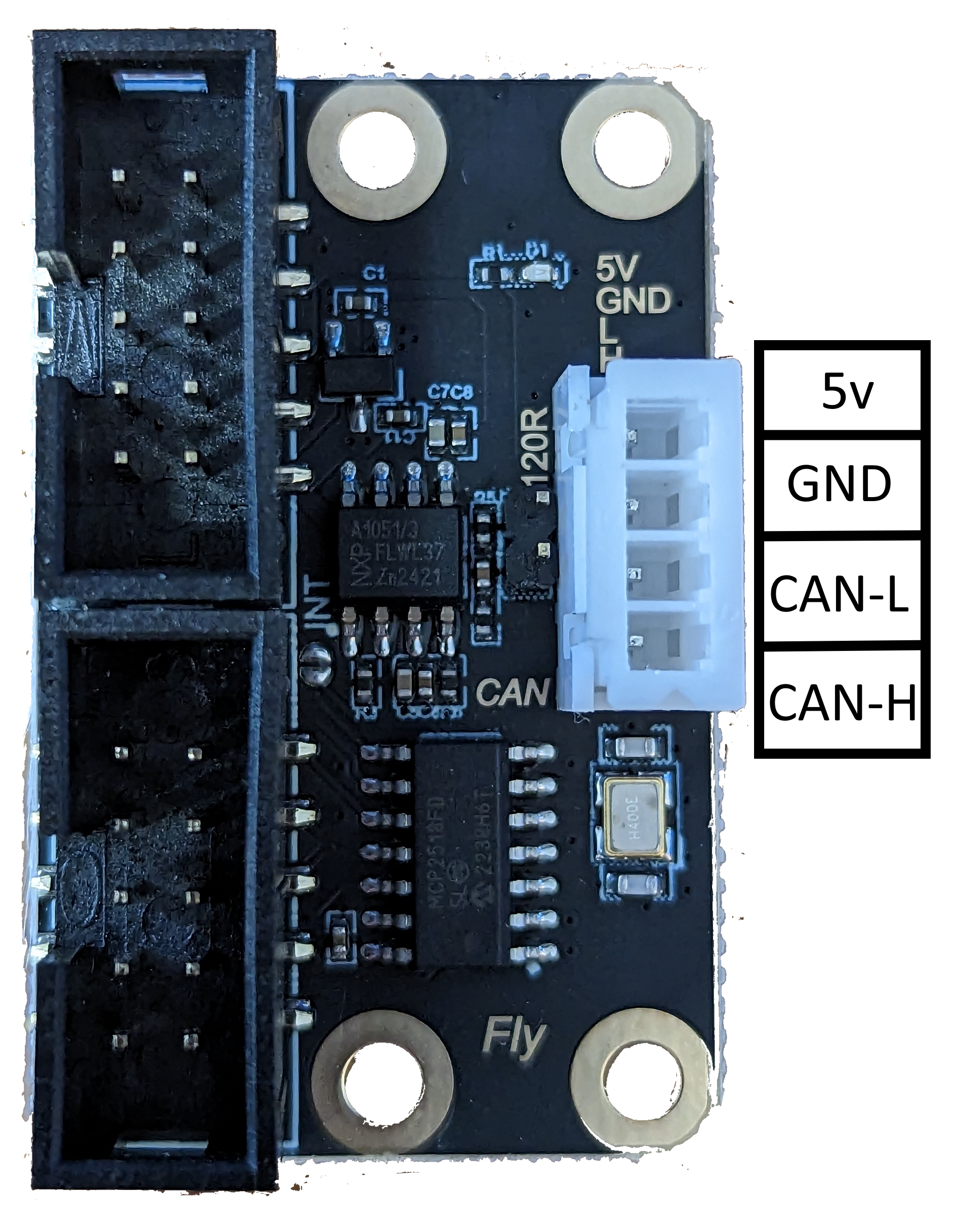
Overview
From 3.5b2, it is now possible to use one or two toolboards with an STM32F4 based board using the CAN-FD protocol. To do so, you must purchase a separate SPI to CAN-FD module. TeamGloomy have worked with Flymaker/Mellow to produce 2 designs of module to suit the board you are using.
For the SKR v2.0 we recommend the EXP1/EXP2 module, which can be purchased from Aliexpress.
Connecting the EXP1/EXP2 module (EFD)
The type of module shouldn’t be shared with a 12864 display.
Connect the EXP1 header on the module to EXP1 on the board. Connect the EXP2 header to EXP2 on the board.
Wiring for the driver module
CAN-FD only requires 2 wires to be connected between each board, CAN-H and CAN-L.
We recommend using stranded twisted wire pairs, such as those found in ethernet patch cables.
Using the image below, the CAN-H connection should be connected to CAN-H on the toolboard. The CAN-L connection should be connected to CAN-L. A jumper should be added to the pins highlighted by the red box.

Board.txt changes
The following two lines should be added to board.txt
//CAN-FD Interface
can.csPin = PA_4
can.spiChannel = 0
Config.g Changes
If successful, the toolboard should show in the object model.
See this page for more information about CAN addresses etc.