Overview
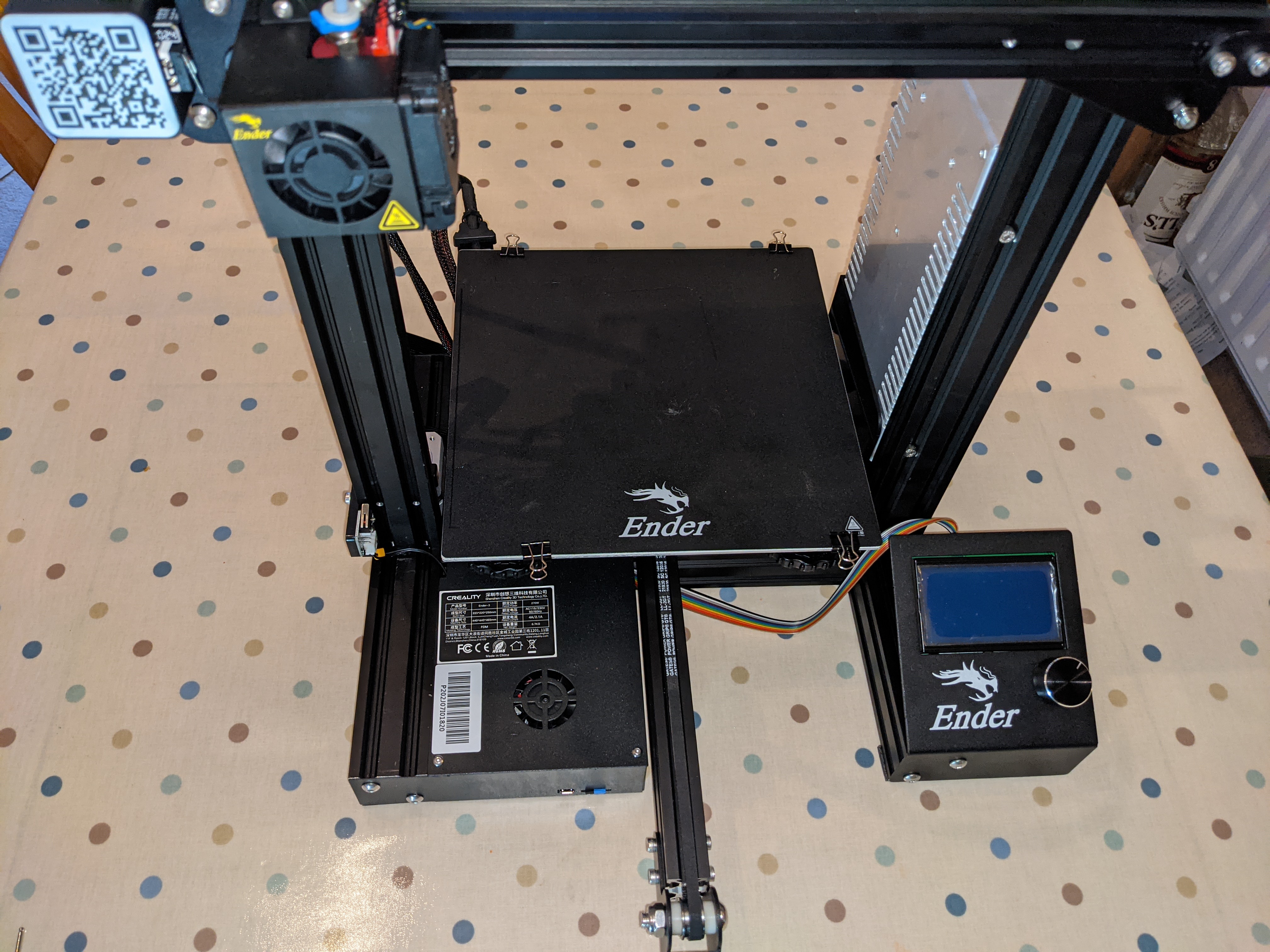
This guide will walk you through converting a stock Ender 3 to RRF using a Fly-E3 board.
Chris’s Basement have also made a video that you can follow in conjunction with this guide.
Tools Required
Below is a list of tools required to complete the job. I have split it into definitely required and advised.
Required
- 2mm Allen Key
- Pliers
- Small Flat Bladed Screwdriver
- Cutters
Advised
Initial Wiring
Step 1
Ensure that the power cable is removed from the power supply.
Step 2
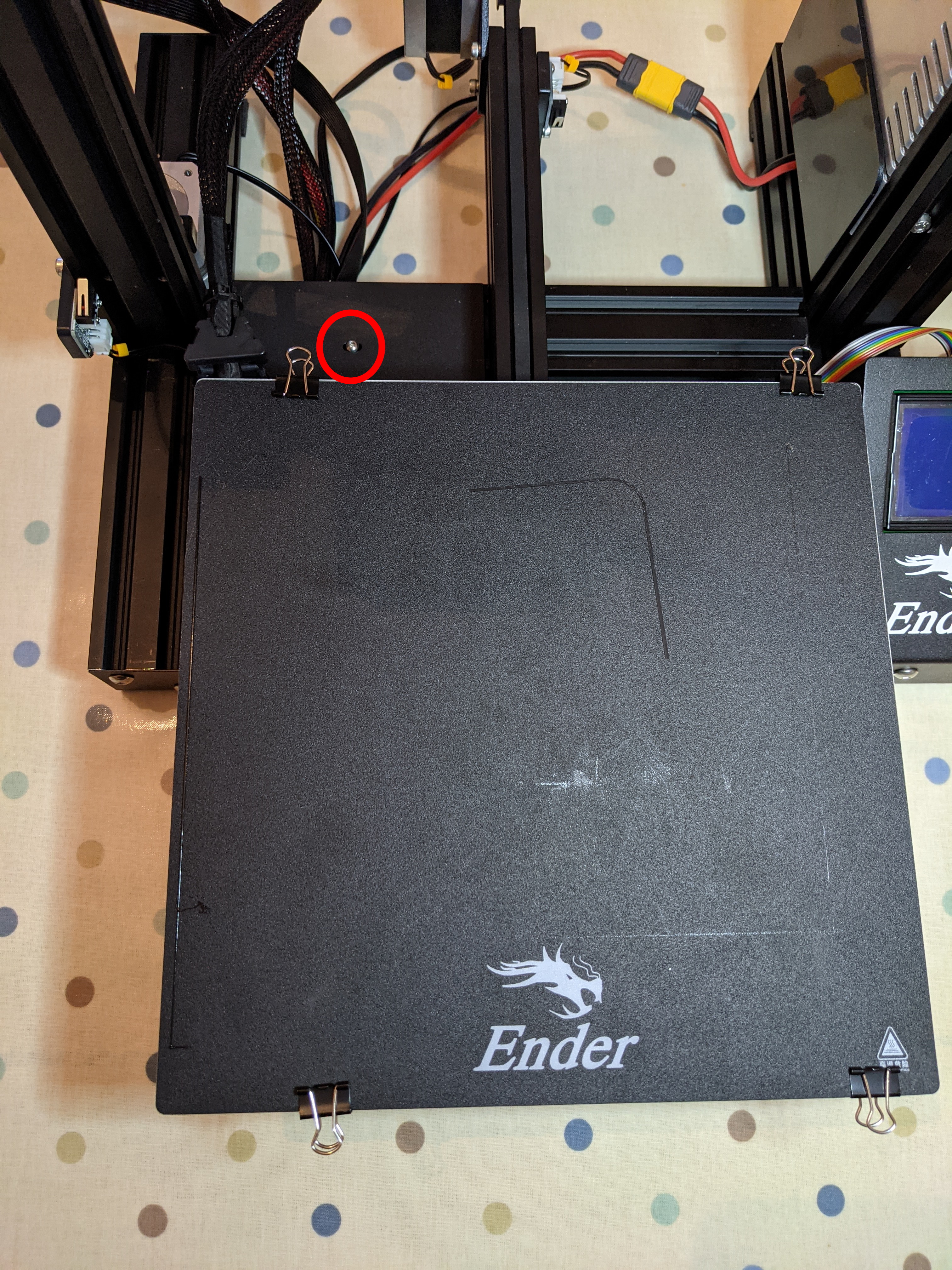
Pull the bed as far forwards as you can.
Using a 2mm allen key, remove the screw highlighted below.
Step 3
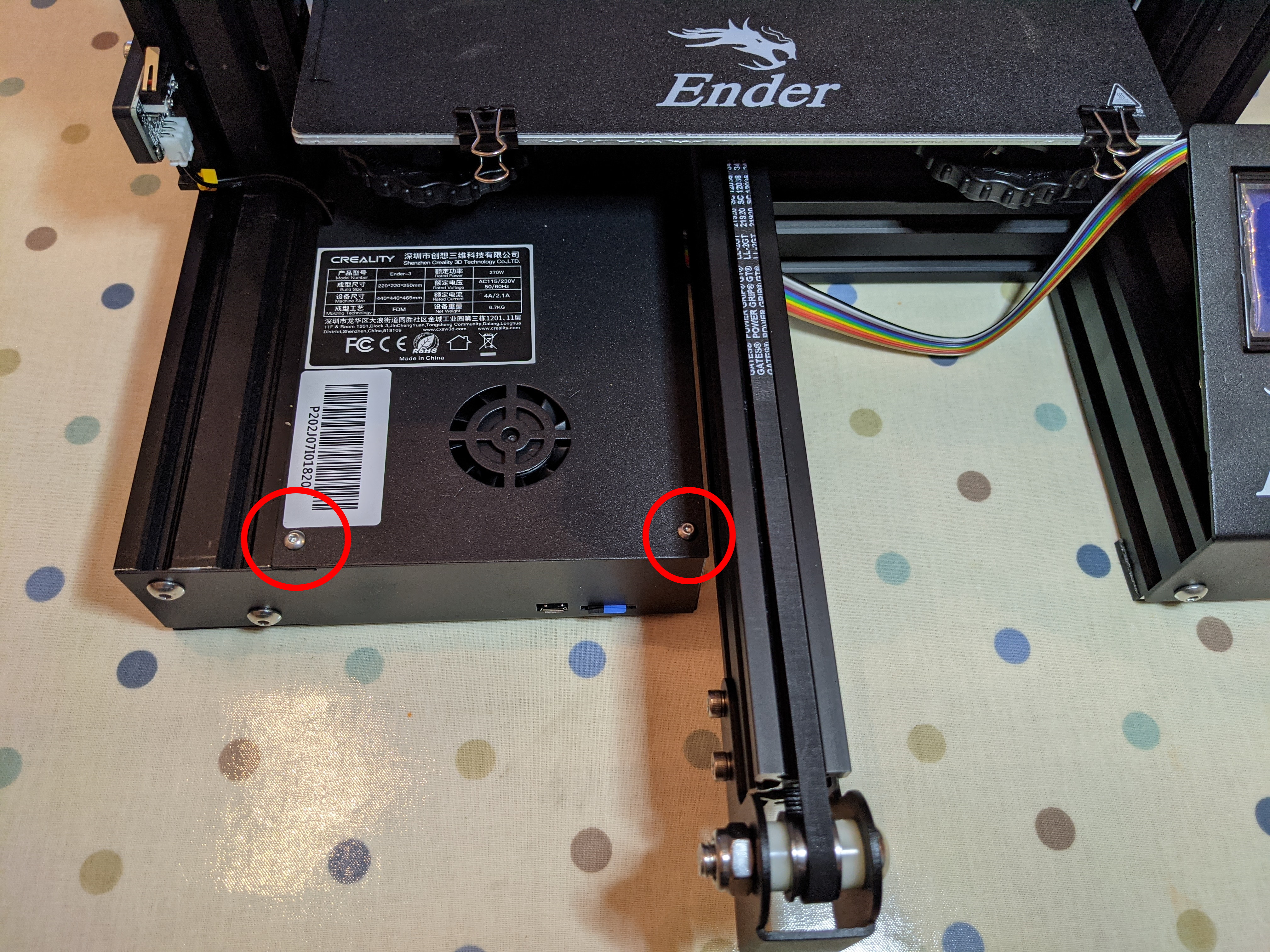
Push the bed back to its maximum position.
Using a 2mm allen key, remove the two screws highlighted below. On the Ender 3 Pro and V2, these can be found on the underside of the case.
Step 4
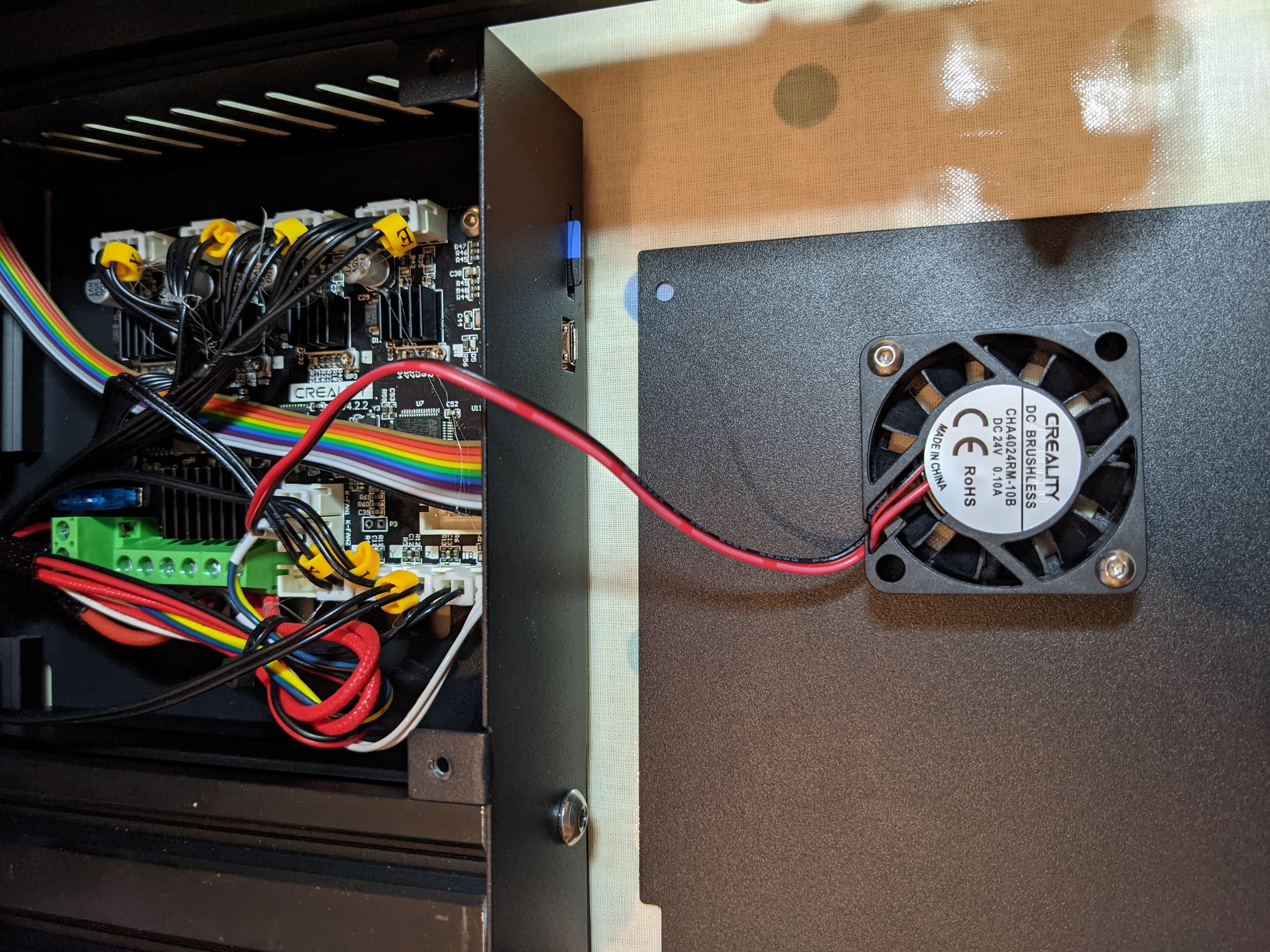
Carefully lift away the cover and lay it down in front of the case. It is attached to the motherboard via the fan cable.
Carefully pull the fan cable out. You can use pliers to assist you if required.
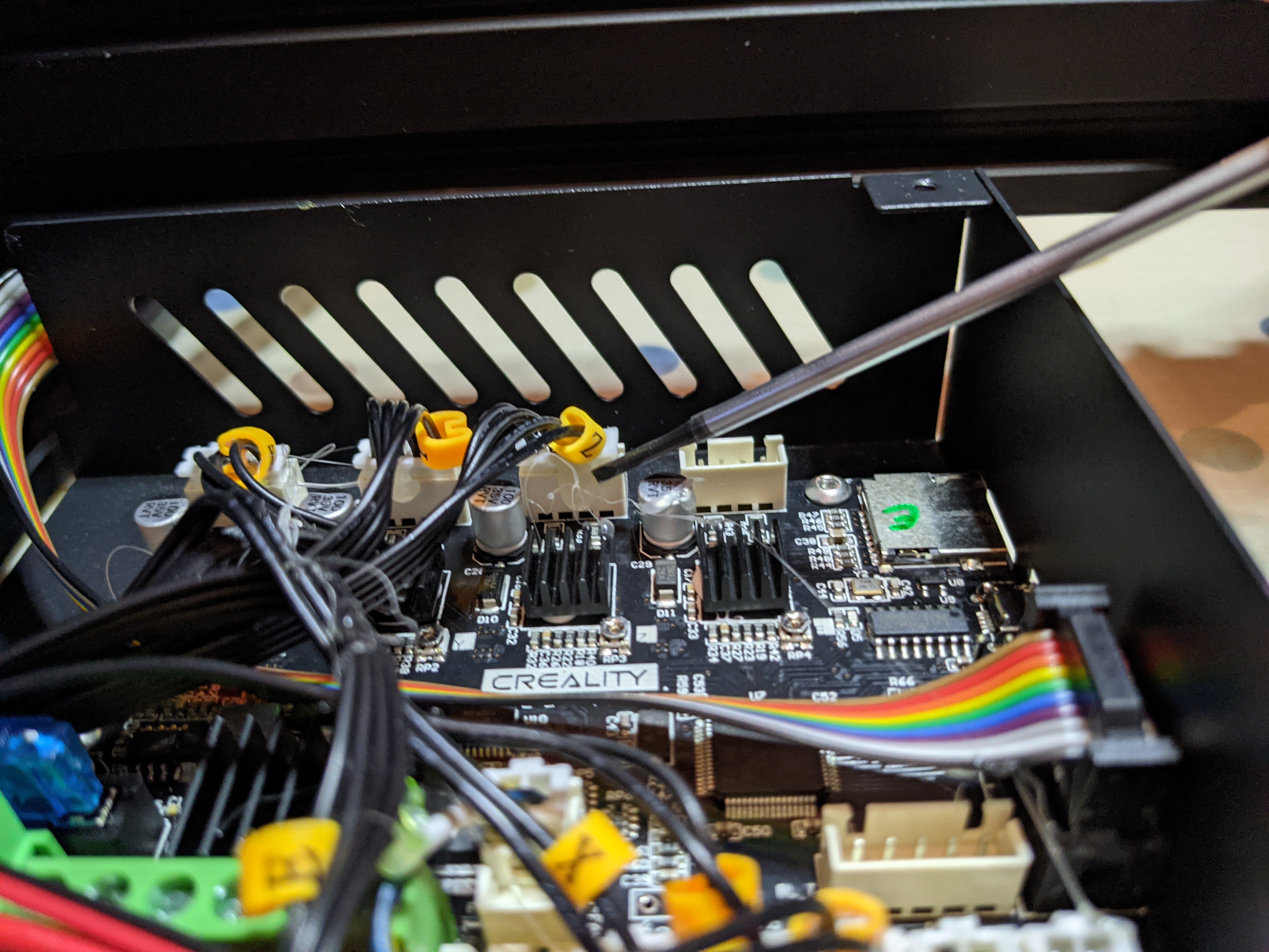
Step 5
Remove the motor cables from the board. You will find that these are held in place using hot glue. Use a small flat bladed screw driver to break the seal on the glue before removing the connector.
All the cables can easily be identified so don’t worry about having to mark them up.
Step 6
Do the same for the connectors on the other side of the board. Again, breaking the seal on the glue to make the connectors easier to remove.
Also remove the ribbon cable for the screen. This should just pull out.
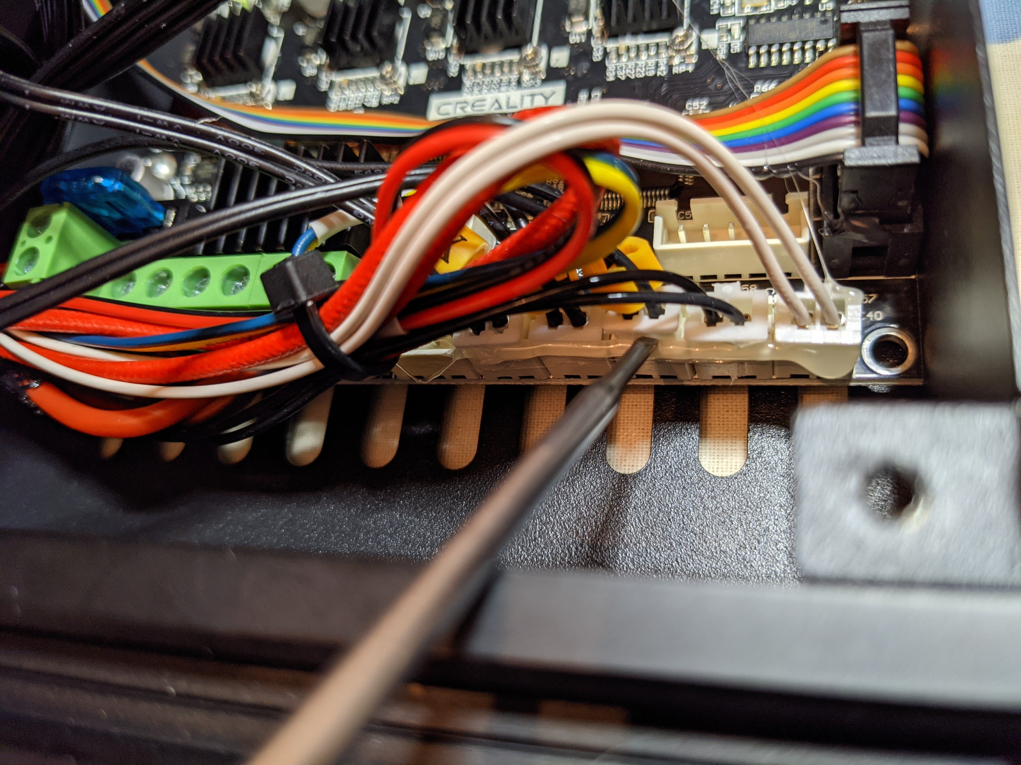
Step 7
Using a small flat bladed screwdriver, undo all the screws in the green connectors and pull out the cables. Again, don’t worry about identification of them.
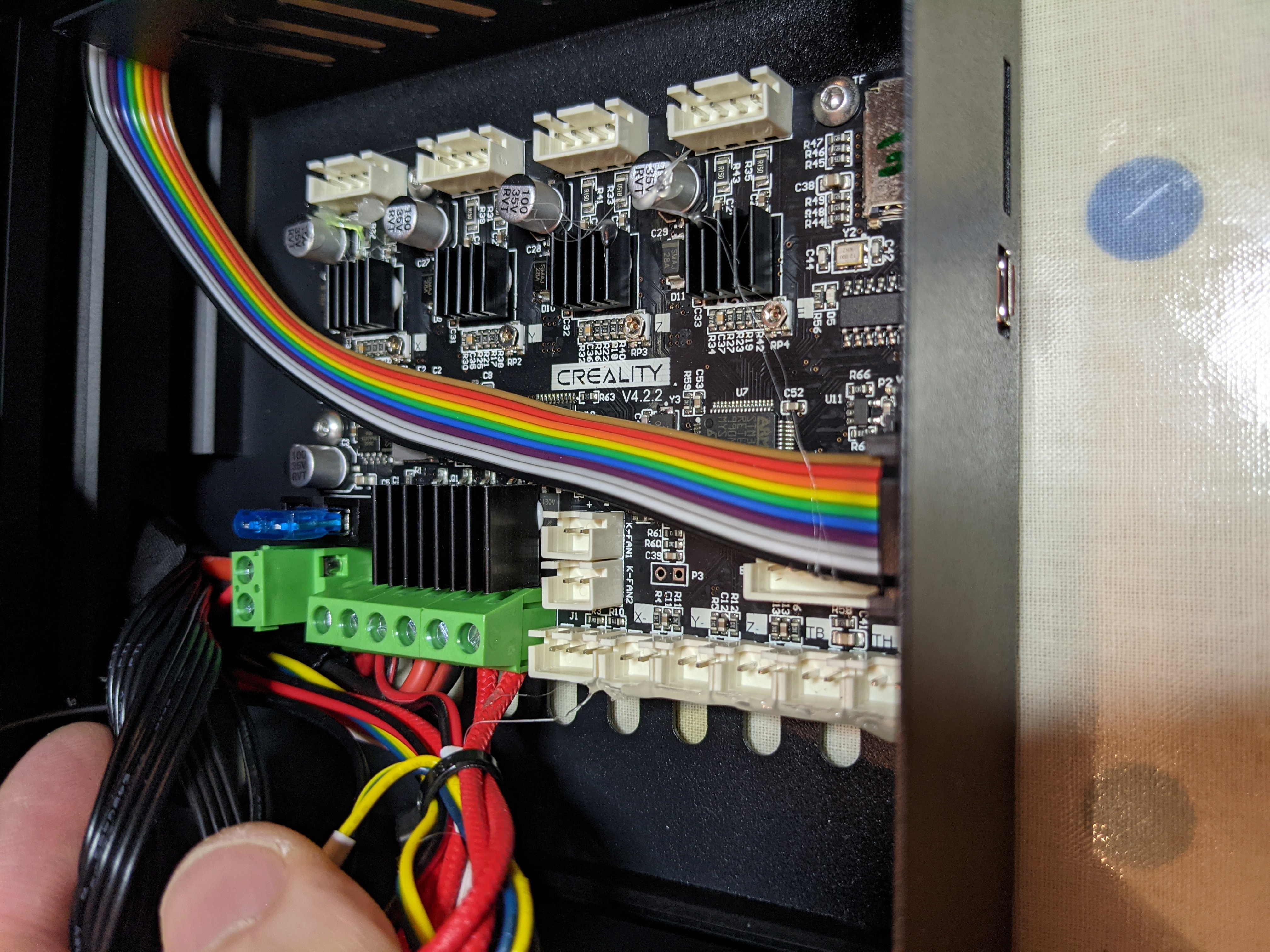
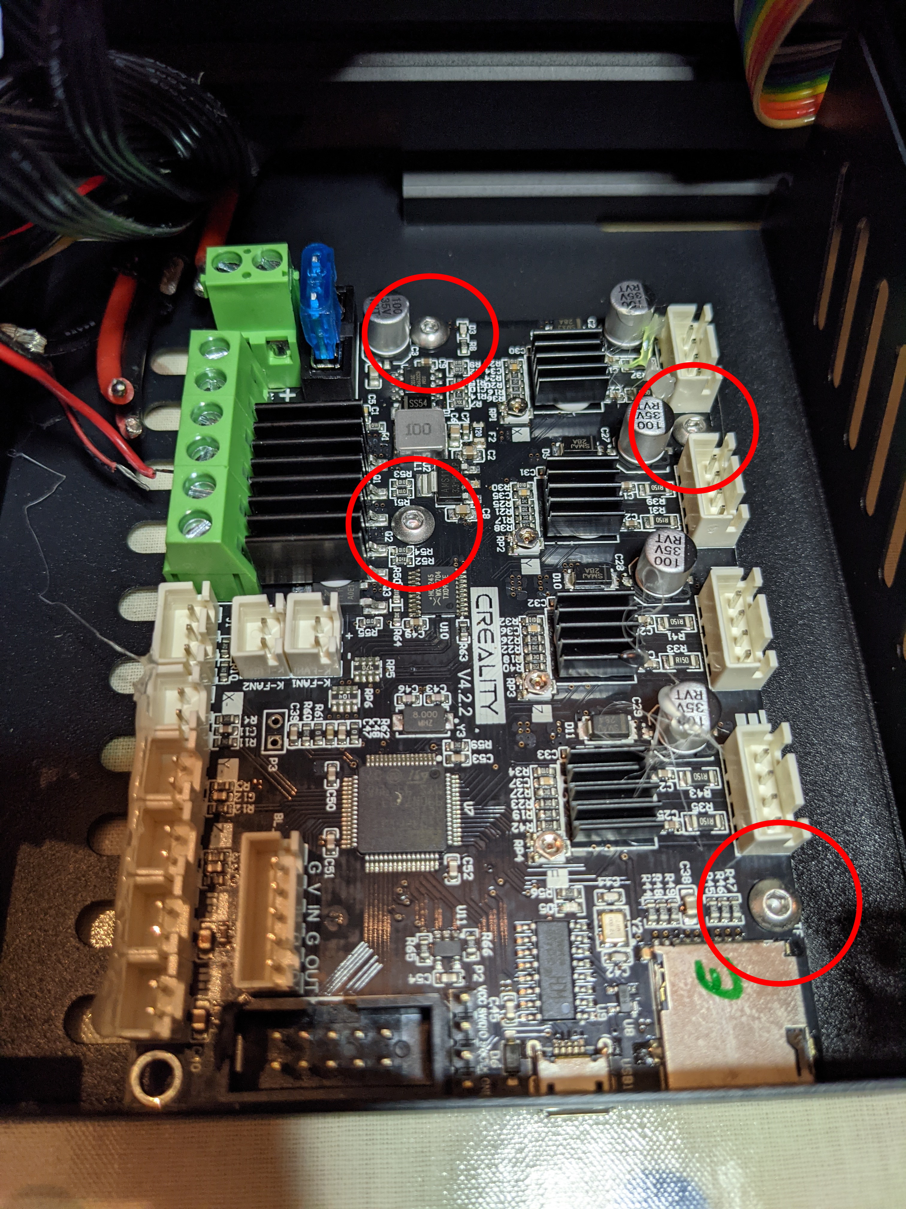
Step 8
Using a 2mm allen key, remove the 4 screws securing the motherboard to the case. Remove the motherboard and put to one side as we won’t be requiring it again.
Step 9
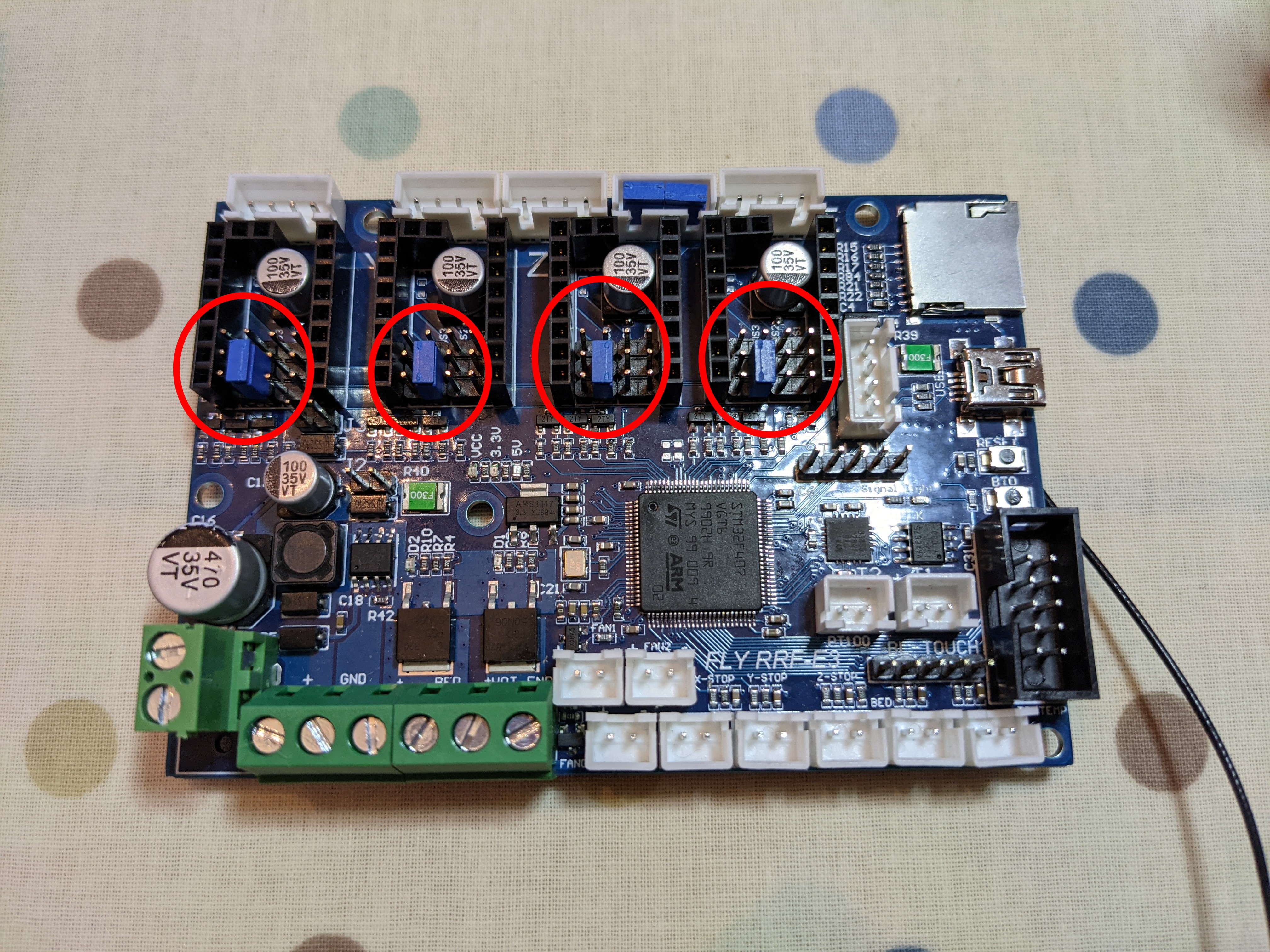
Lay the Fly-E3 down in front of you. The first thing to do is to install a jumper underneath each driver as shown below. This sets the drivers into UART mode so they can be communicated with correctly.
Step 10
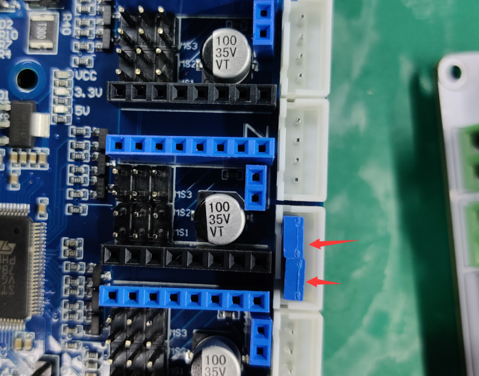
Install jumpers on the other Z output as shown below.
Step 11
Depending on which drivers you are going to use will determine what you do for this step.
Fly Drivers
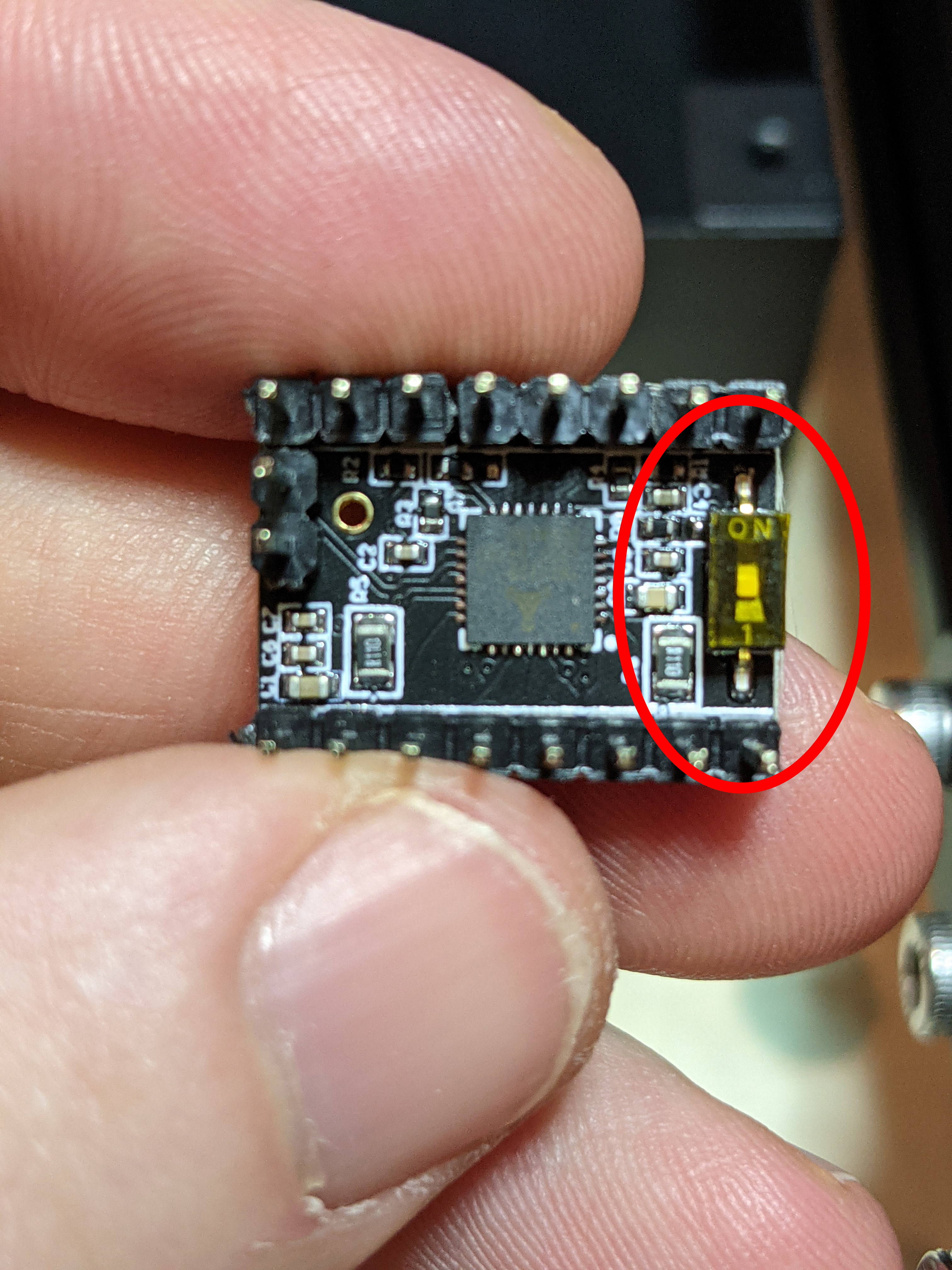
The Fly-2209 drivers come with a small switch on the underside. This is used to enable and disable the diag pin, which is used for sensorless homing. As this is for a stock ender 3 with endstops, we won’t be enabling the diag pin on this occassion. The drivers should come with the switch in the off position but its always good to check anyway.
Non-Fly 2209 and 2226 Drivers
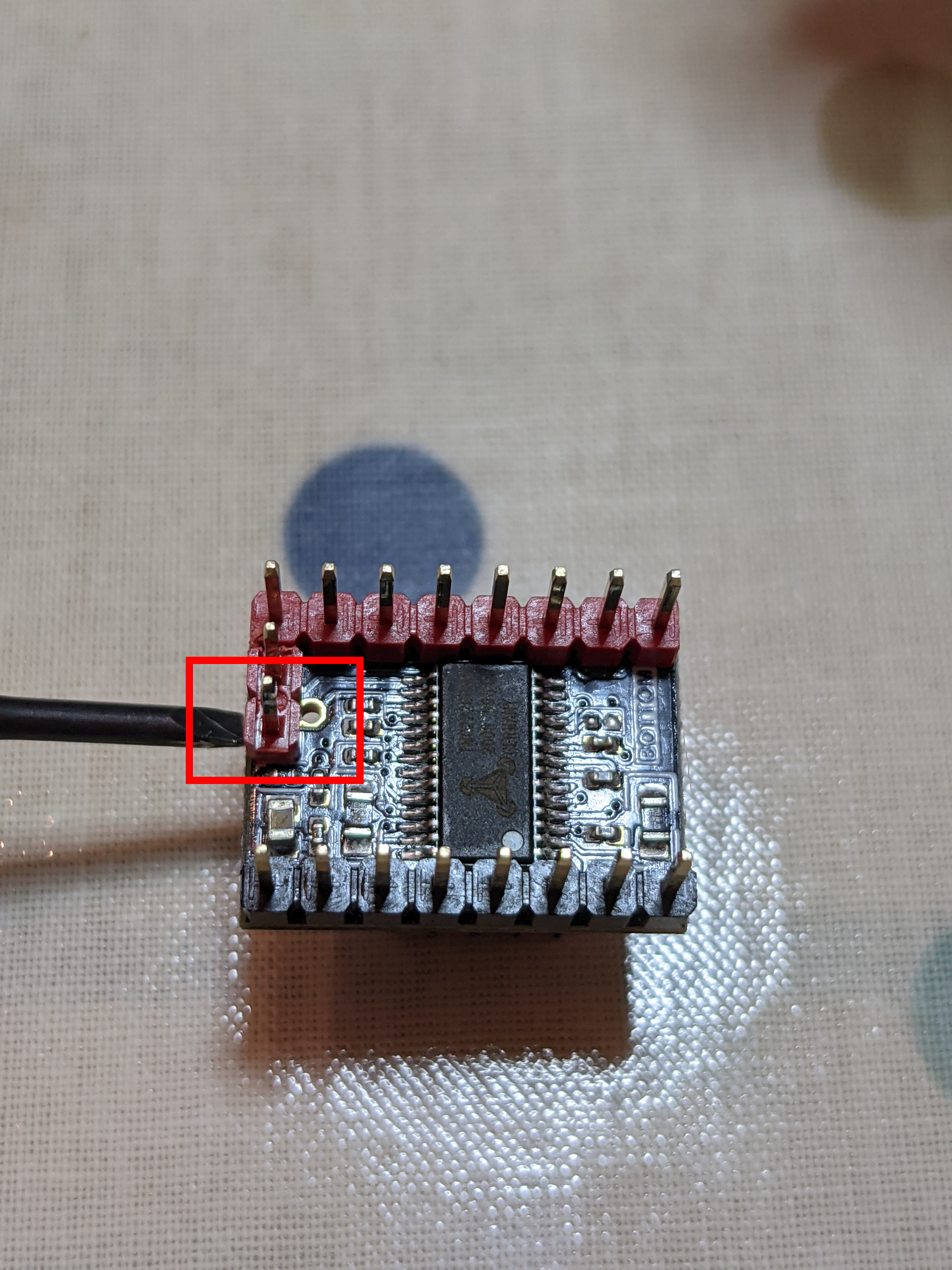
The Fly-E3 does not have a way to enable and disable the diag pin on drivers on the motherboard itself. Its designed to be used with the Fly-2209 driver. Therefore, when not using sensorless homing (and whats the point when you already have endstops installed), the diag pin needs to be removed from the driver for the endstops to function. Using cutters, remove the diag pin from the X, Y and Z stepper drivers.
Step 12
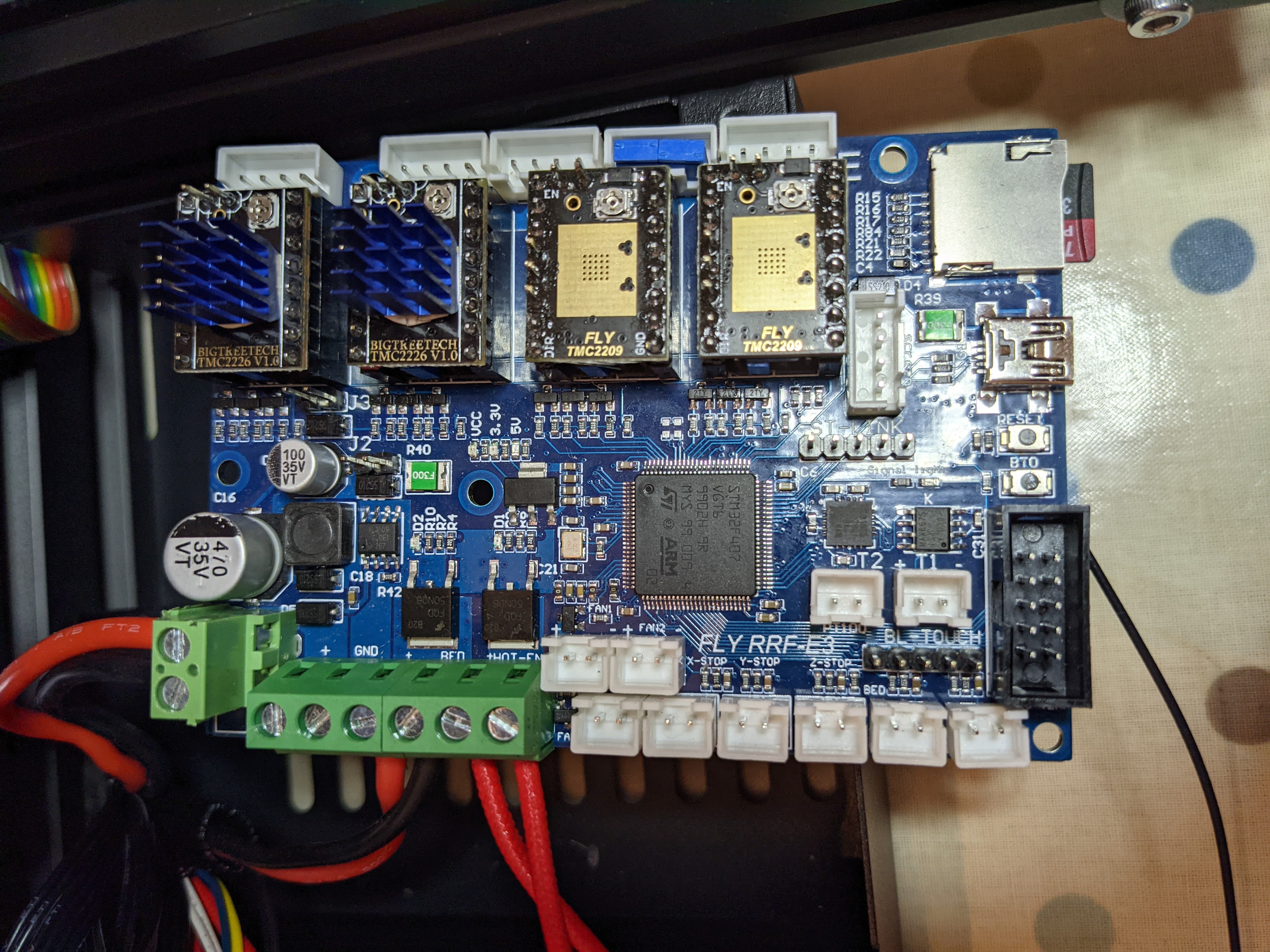
Install the drivers into the Fly-E3. You will have been supplied with two heatsinks with the Fly-E3. These are to be installed on top of the drivers installed in Z and E. This is because with full sized heatsinks, the cover can’t be installed with the fan attached.
Step 13
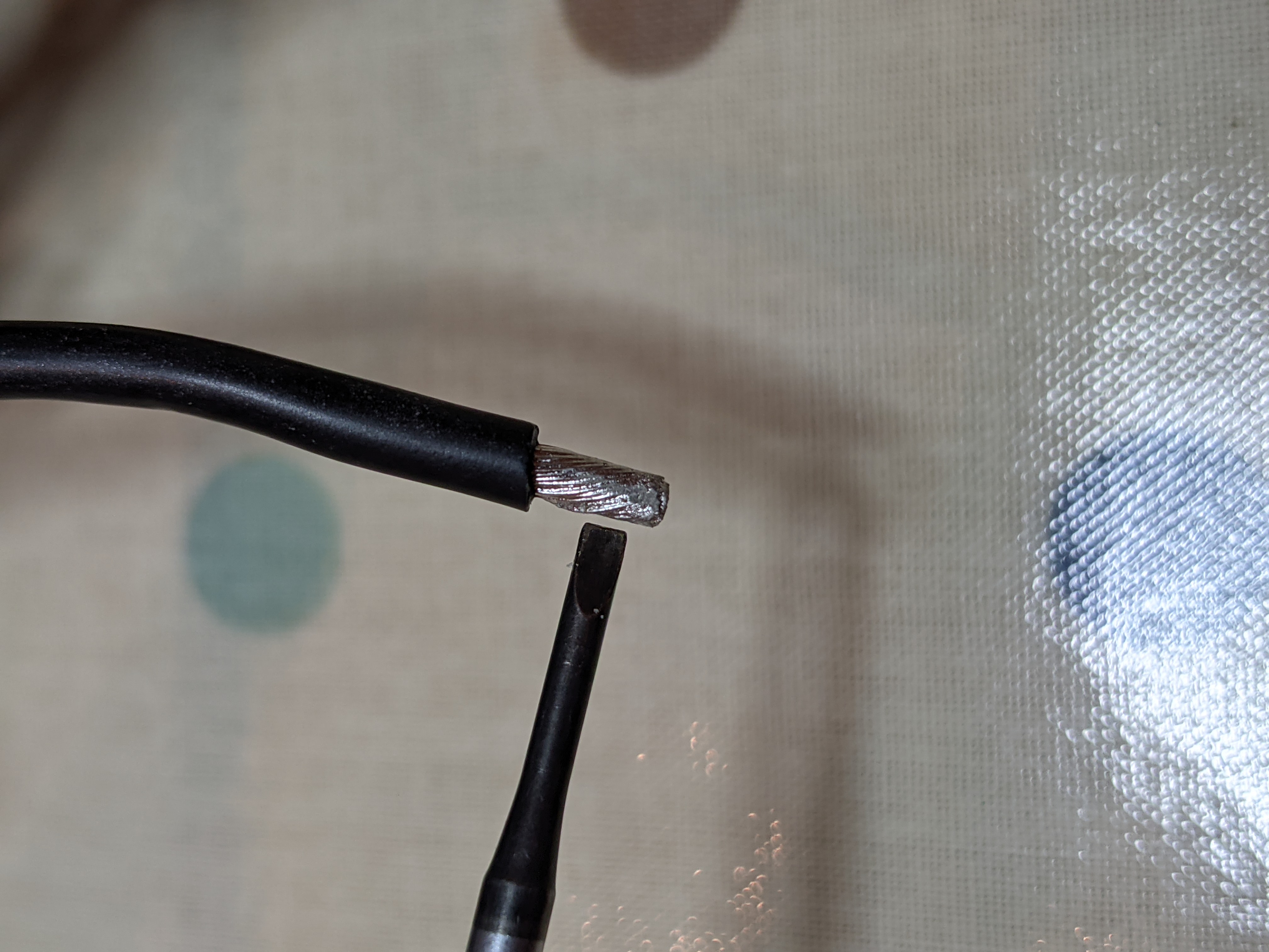
Creality have, in their infinite wisdom, tinned the ends of the power cables and bed cables using solder (shown below). This is a bad idea as it can lead to cables that can break more easily and if the connection becomes hot, the solder can soften, reducing the force on the contact from the terminal, eventually resulting in shorts and fire. Here is a document for more detail about the issue.
Step 14
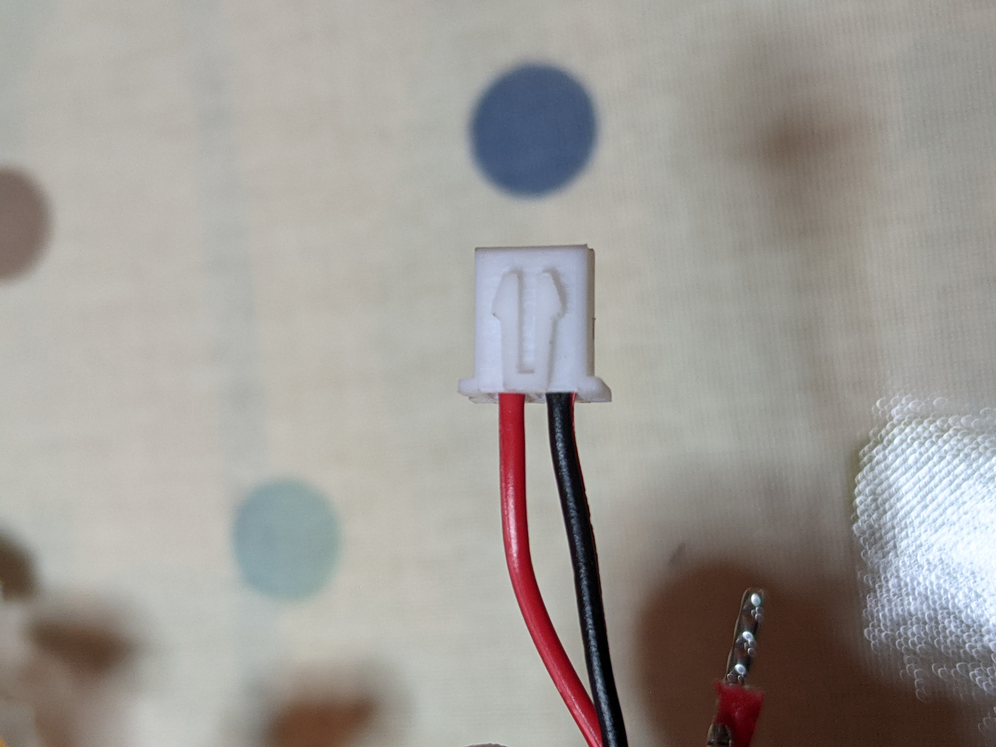
On a stock Ender 3, the hotend cooling fan is wired to be permanently running when power to the system is applied. If you are happy with the arrangement, then you can skip this step. If you prefer that your hotend fan is only on when the hotend is on, then you’ll need to crimp a new connector on the end. As with the ferrules, sets can be purchased on Amazon.
Crimp the connectors on to the thin red and black cables (the only free cables left that we didn’t add ferrules to) and insert them into the housing as shown below.
Step 15
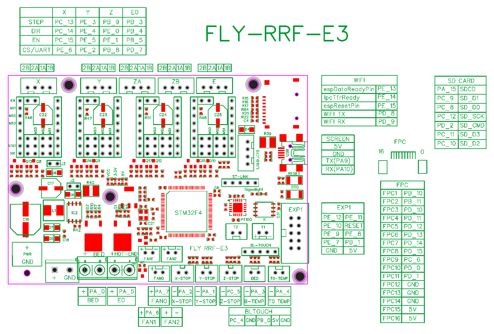
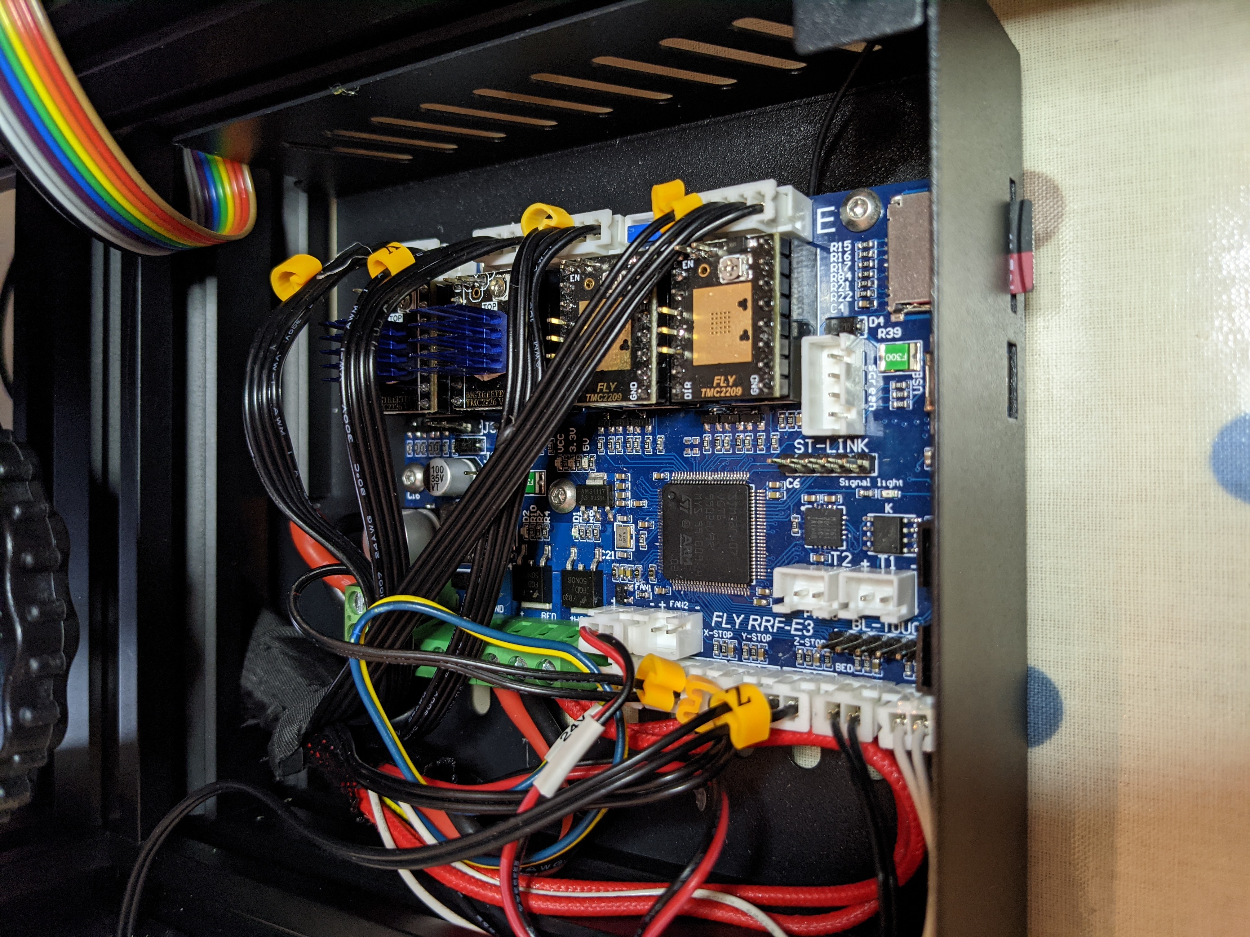
I found that it was much easier to install the cables in the terminal blocks before installing the board back into the case. Therefore install the power cables (paying attention to the polarity), the hotend fan (if not following the step before), the bed cables and the hotend cables. They should match the image below. Remember, the first two terminals out of the 6 (the ones closest to the power input terminal) are always powered and should only be used for the hotend fan if you are not going for thermostatic control as per step 13.
Step 16
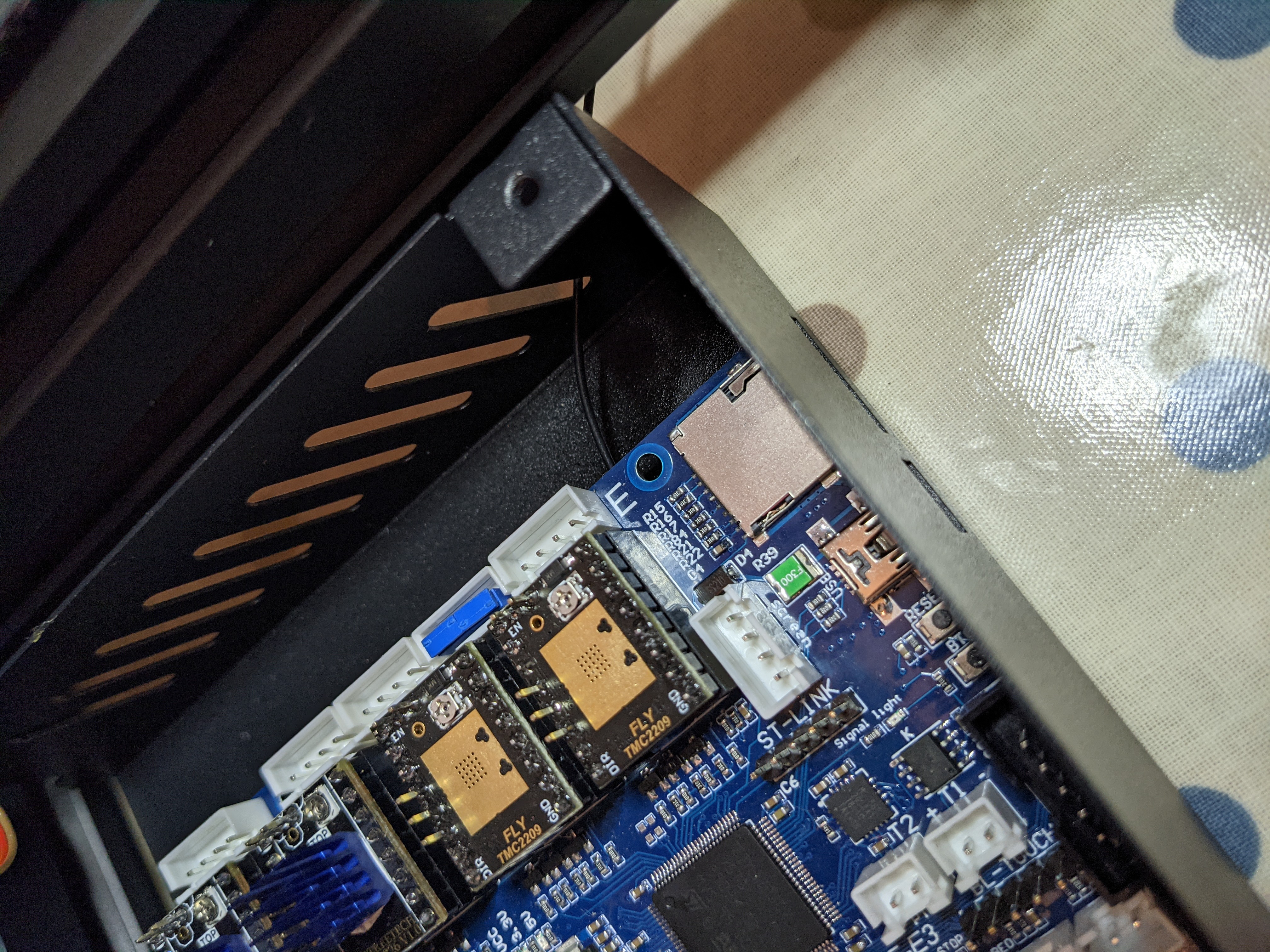
Feed the antenna for the WiFi through the first slot in the side of the case.
Step 17
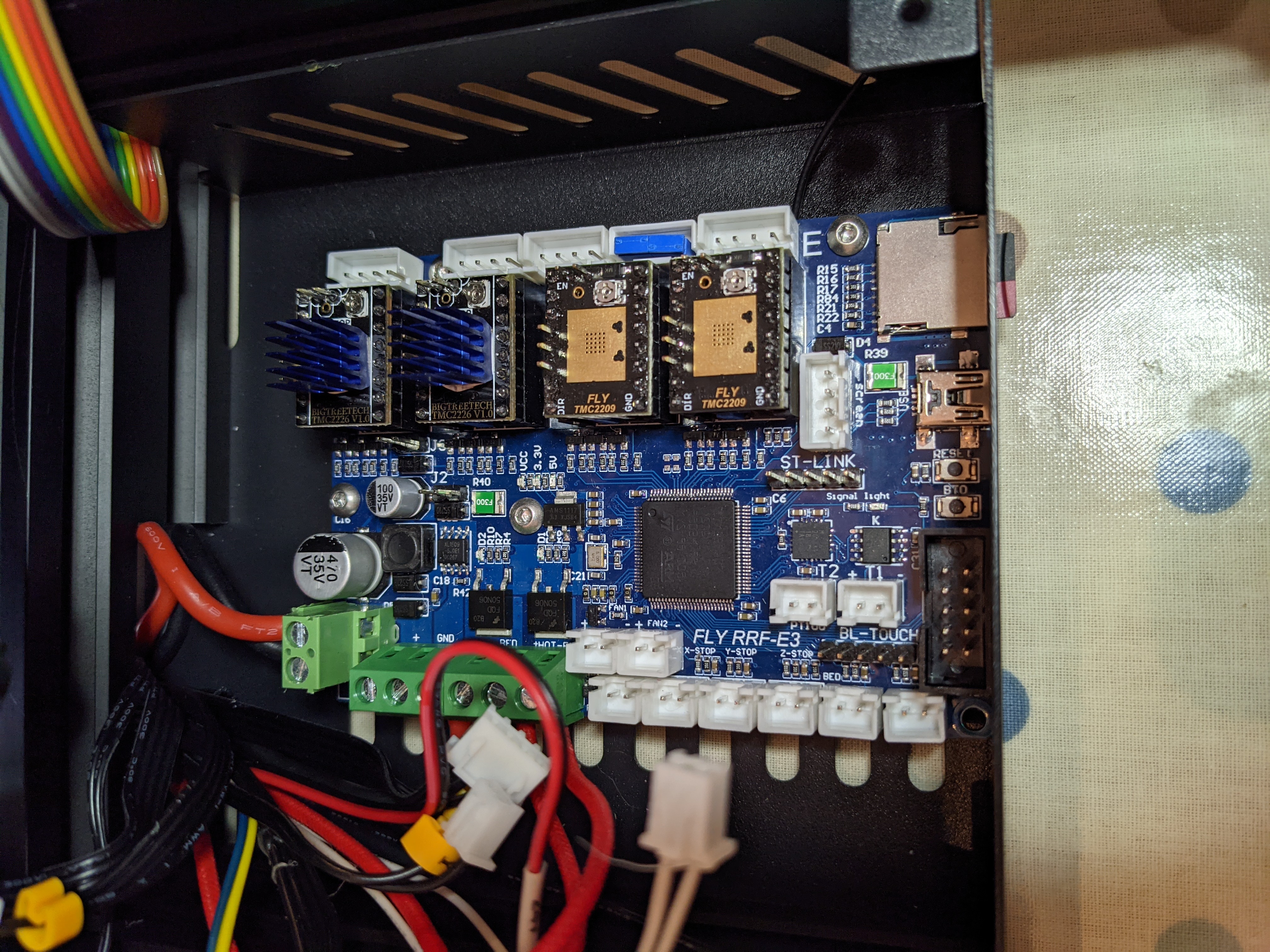
Install the board into the case, using the screws that you removed earlier.
Step 18
Connect the remainder of the cables to the board. The fan with the yellow and blue cables should be connected to Fan0. If you installed a JST connector to the hotend fan, install it in the Fan1 slot. The connector with the two black cables is the bed thermistor and the connector with the two white cables is the hotend thermistor. Please use the pinout for reference. None of the stock Ender 3 cables require adapting.
Step 19
Reconnect the power to the power supply and then we will move on to preparing the software.
Software configuration
SD Card formatting
Format the SD card that came with the SD Memory Card Formatter.
SD Card Contents
Download the files contained on our repo and place them on the SD card.
Download the latest firmware (called firmware-stm32f4-esp8266wifi-XXX.bin) from here. Rename it firmware.bin and put it on the root of the SD card.
Download the latest WiFi firmware (called DuetWiFiServer-esp8266-stm32f4.bin) from here. Rename it to DuetWiFiServer.bin and put it in the sys folder on the SD card.
Download the latest DWC from here. Extract the contents to a folder called “www” on the root of the SD card.
Firmware Flashing
Take the SD card you prepared and put it in the Fly-E3.
Turn on the printer.
Connect your computer to the Fly-E3. Please be aware of ground loops. It is advised to power both the PC and Printer from the same double socket, or if possible, use a laptop.
After 10 seconds or so, the Fly-E3 should become accessible to the PC.
Identifying the COM Port of the Fly-E3
Method 1
Follow the information on this page to identify the COM port of the Fly-E3.
Method 2
Install this piece of software. Then, when you connect a device that creates a COM Port, a popup will appear telling you the COM Port number.
Connecting to the Fly-E3 by Terminal
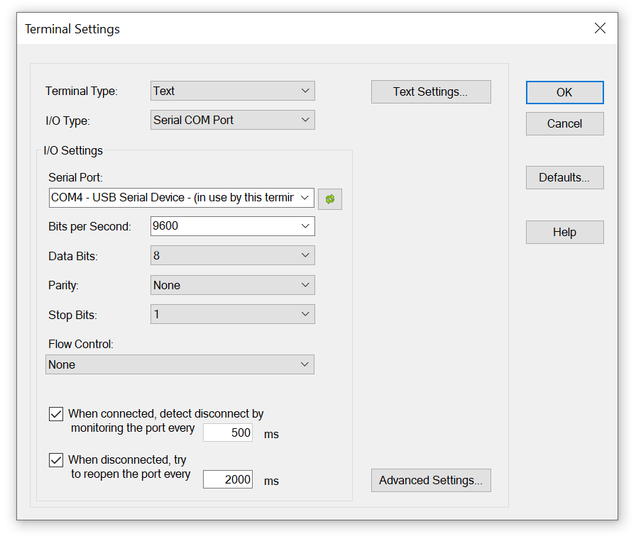
This instruction is written around using YAT, but other terminal software can be used.
On opening the software, a screen will ask you which serial connection to connect to. Select the one you identified from above. The standard settings of 9600 etc are correct.
Type M115 to confirm that RRF has been installed.
Then type in the following
M997 S1
Wait for the uploading of the WiFi firmware to finish. Then send the following
M552 S0
M587 S"your SSID" P"your password"
M552 S1
When the connection has been established, the IP address of the Fly-E3 will be displayed. Make a note of this and disconnect your PC/Laptop.
Final Steps
Open your favourite web browser and type in the IP address that was displayed in the terminal. DWC (Duet Web Control) should then load, giving you full control over your machine.
Navigate to the systems tab. Click on “config.g” and check it to make sure that there is a line that says M552 S1. If there isn’t or there is another variant of M552, change it to M552 S1 and click save. Then yes. After a short period (less that 30 seconds), the web interface should reload. If it doesn’t, remove the SD card and make sure your config.g has M552 S1 (its in the sys folder).
Endstops
Check the status of the endstops using M119. Each endstop should display “not stopped” (assuming that they are not currently being triggered). Trigger each endstop and while holding them in, send M119. Each one in turn should show as “at min stop”.
If that hasn’t been successful, check that everything is fully seated (remembering to turn the power off before hand.).
Homing
Now try homing the printer. The axis should move in the correct direction for the Ender 3 cabling, but make sure you are near the emergency stop button on the web interface or the power button just in case.
Tuning
Now you should tune the bed and the hotend.
For the bed, run the following command.
M303 H0 S60
That will tune the bed to 60 degrees. Please take into account that it may take up to an hour to run.
Once its completed, type M500. If you get a warning that M501 isn’t in your config.g, add it to the end.
Then tune the hotend. Jog the nozzle so it is near to the print surface then run the following command.
M303 T0 S220
That will tune the hot end to 220 degrees. The part cooling fan will be turned on automatically half way through the process.
Once its completed, type M500.
Bed Levelling
Screw the levelling screws in to pull the bed down. Using DWC, set the bed temperature to 60 degrees and the hotend to 200.
Run the manual bed levelling macro included on the macros tab.
This will move over the 4 screws securing the bed in place. Using DWC or the screen, jog the Z axis down to 0. Then, with a piece of paper between the nozzle and the bed, wind the bed levelling screws out until the nozzle just grips the paper. Do this in the orher 3 corners.
Fitting the cover
Turn off the printer and remove the power lead.
Plug the fan on the cover into fan2 and secure the cover in place using the 3 screws (the long one goes to the back).
Finished
Thats it.
Set up your favourite slicing software, remembering to set relative extrusion, firmware retraction and reprap or reprapfirmware as the type of gcode to output.
Some slicers support automatic uploading (prusa slicer has it built in, cura has a plugin).