Overview
From 3.5b2, it is now possible to use one or two toolboards with an STM32F4 based board using the CAN-FD protocol. To do so, you must purchase a separate SPI to CAN-FD module. TeamGloomy have worked with Flymaker/Mellow to produce 2 designs of module to suit the board you are using.
For the BTT Octopus Pro v1.0 F429 Version you can use both the DFD module (which plugs into a driver socket) and the EFD module (which plugs into EXP1/EXP2), both of which can be purchased from AliExpress.
Connecting the driver module (DFD)
You need either a spare driver slot or you replace an extruder driver with a toolboard. The driver slot should ideally be the last one on the board and have a working voltage of 24v.
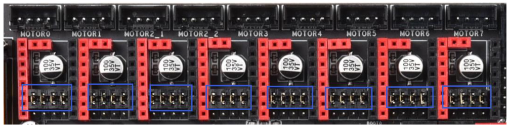
The driver slot you are going to use should be put in SPI mode. This is done using jumpers as shown below.
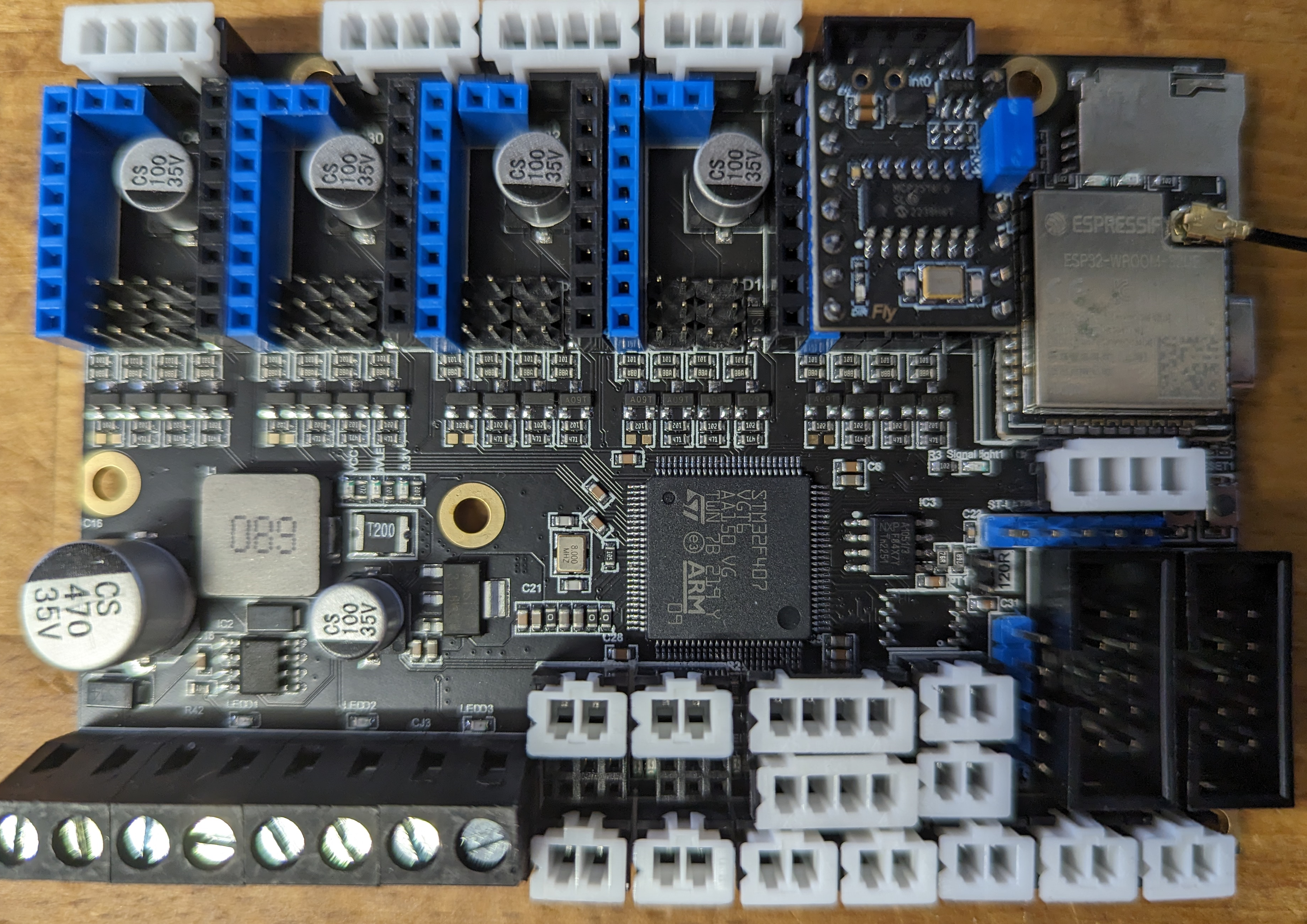
Install the driver module. Ensure the module is installed so the hole thats in the same position as the diag pin is closest to the driver socket.
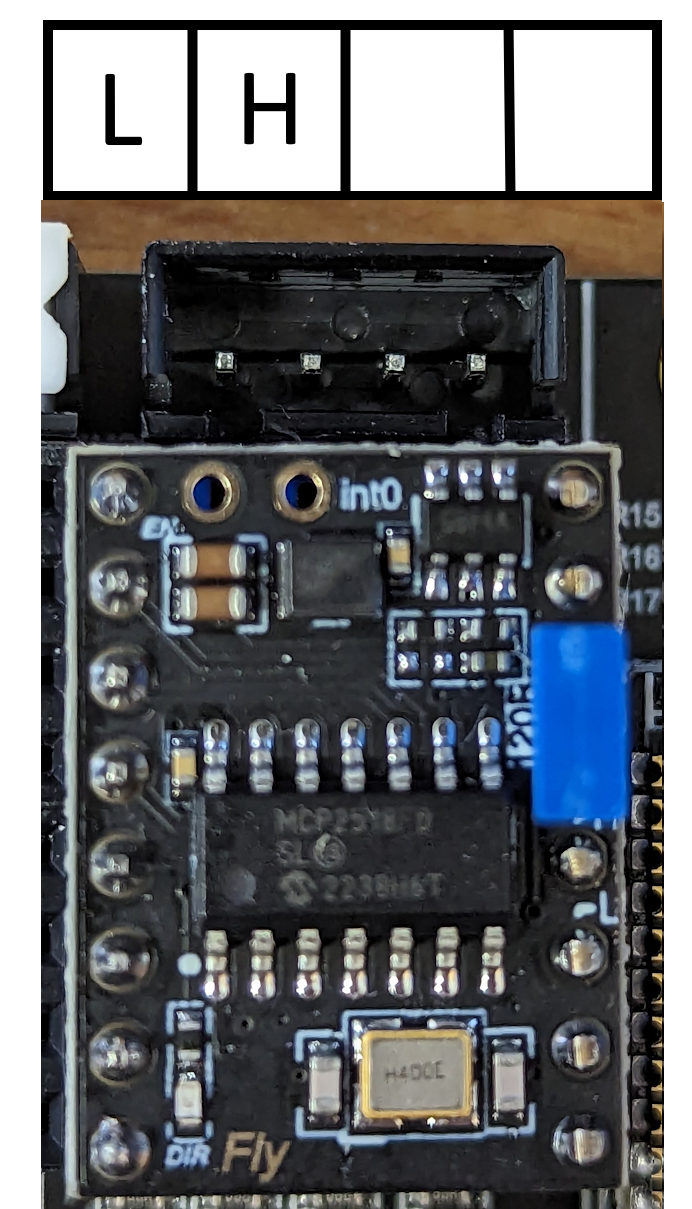
Also make sure you install the jumper as shown below.
Wiring for the driver module
CAN-FD only requires 2 wires to be connected between each board, CAN-H and CAN-L.
We recommend using stranded twisted wire pairs, such as those found in ethernet patch cables.
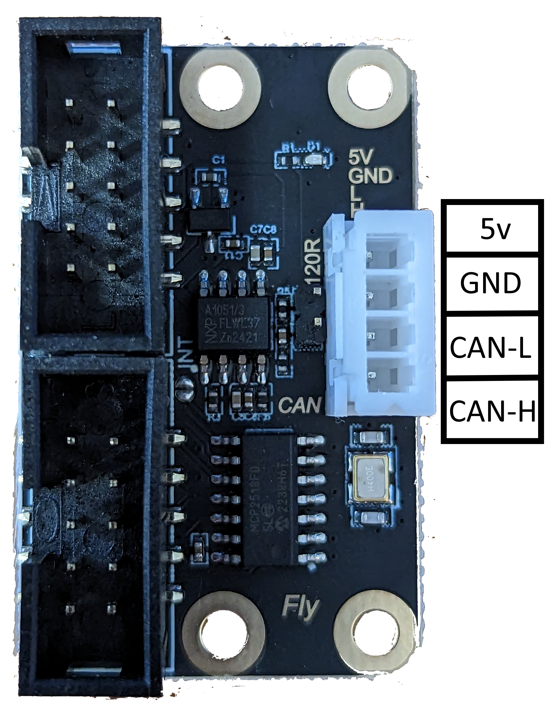
Using the image below, the H connection is the CAN-H connection and should be connected to CAN-H on the toolboard. L is the CAN-L connection and should be connected to CAN-L.
Board.txt changes
The following two lines should be added to board.txt and assume the last driver slot is used. If another driver slot is used the appropriate CS pin must be chosen.
If you do not have a board.txt file in sys (the same location as config.g), create one using DWC.
//CAN-FD Interface
can.csPin = PD_3
can.spiChannel = 0
Don’t forget to reduce the number of smart drivers if you are replacing a driver with the drive SPI to CAN-FD module.
If you are running the DFD module at the same time as 5160 drivers, it is recommended to slow down the SPI connection. To do so, add the following line to your board.txt.
can.spiFrequencyHz = 10000000
Config.g Changes
If successful, the toolboard should show in the object model.
See this page for more information about CAN addresses etc.
Connecting the EXP1/EXP2 module (EFD)
The type of module shouldn’t be shared with a 12864 display.
Connect the EXP1 header on the module to EXP1 on the board. Connect the EXP2 header to EXP2 on the board.
Wiring for the driver module
CAN-FD only requires 2 wires to be connected between each board, CAN-H and CAN-L.
We recommend using stranded twisted wire pairs, such as those found in ethernet patch cables.
Using the image below, the CAN-H connection should be connected to CAN-H on the toolboard. The CAN-L connection should be connected to CAN-L. A jumper should be added to the pins highlighted by the red box.
Board.txt changes
The following two lines should be added to board.txt.
If you do not have a board.txt file in sys (the same location as config.g), create one using DWC.
//CAN-FD Interface
can.csPin = PA_4
can.spiChannel = 0
Config.g Changes
If successful, the toolboard should show in the object model.
See this page for more information about CAN addresses etc.