Overview
This page covers any general information for the Fly-Gemini-V2 board.
It is currently available through AliExpress.
Board.txt Name
The board name in board.txt is fly_geminiv2.0.
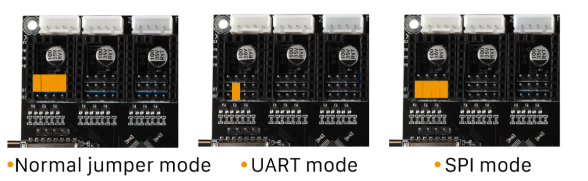
Driver Jumpers
The jumpers should be installed as below. “Common Interpolation” should be used for standalone drivers. “SPI mode Interpolation” is supported for TMC5160 drivers. “UART mode Interpolation” should be used when using smart drivers (i.e. TMC2208, TMC2209, TMC2225 and TMC2226)
Driver Diag Pin
The driver diag pin is used for sensorless homing and stall detection.
The Fly-Gemini-V2 does not have a way of disabling the diag pin as it is designed to be used with Fly-2209 drivers which have a switch on the underside of them for disabling the diag pin.
If you plan on using endstops rather than sensorless homing and do not have the Fly-2209 drivers, you need to bend or remove the diag pin.
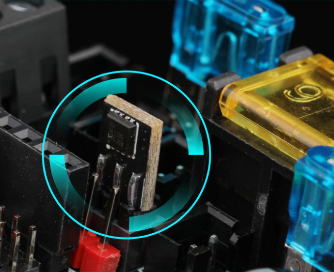
Fan Mosfets
The Fly-Gemini-V2 fan mosfets are replaceable. Each mosfet (VS3622e) controls two of the fan outputs. The orientation that the fan mostfet is plugged into the board doesn’t matter.
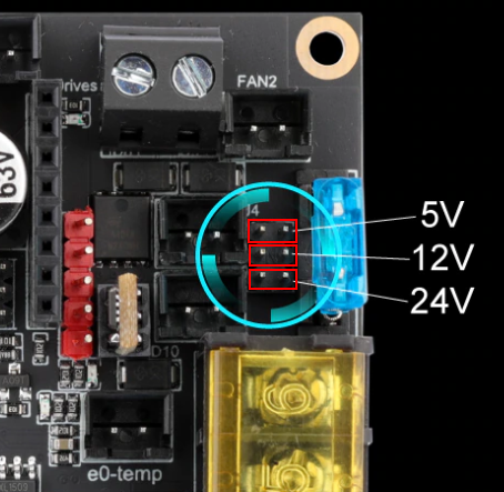
Fan Voltage
The fan voltage can be set using jumpers to either 5v, 12v and Vin.
Set them as shown below.
Maximum Input voltage
Board/Bed Power
The board can handle an input voltage up to 30v.
Driver Power
The board can handle an input voltage up to 62v.
Initial Installation
The board that you will receive doesn’t have any firmware installed so when plugged into a computer, the board will show as an unidentified device. Follow the SBC instructions.