Overview
This page covers any general information for the Fly-E3-Pro-v3 board.
It is currently available through AliExpress.
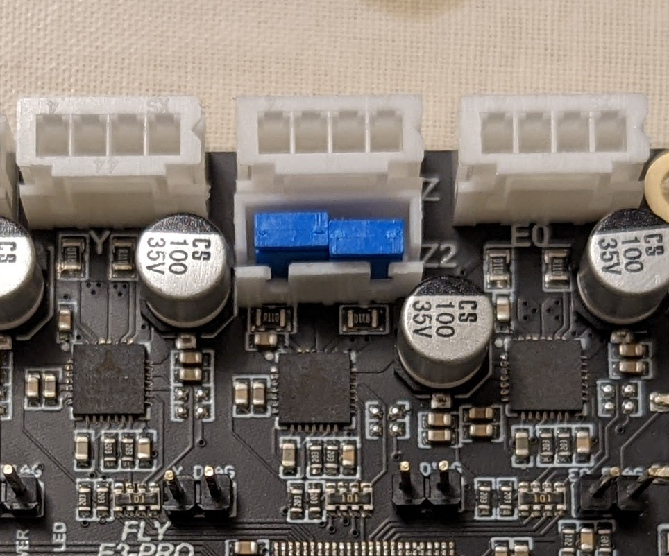
Z Driver Jumpers
If only one Z output is being used, jumpers should be installed on the other Z output as shown below.
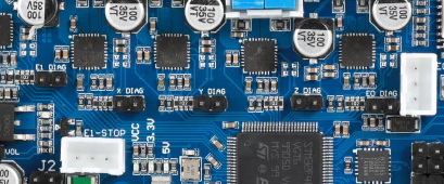
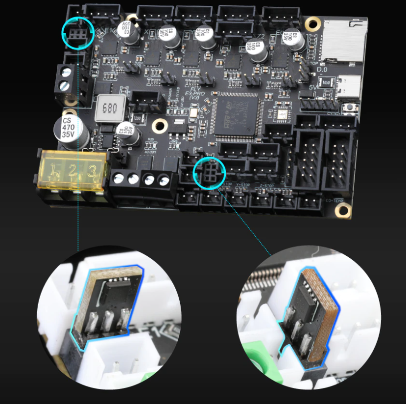
Driver Diag Pin
To use sensorless homing, a jumper must be installed on the diag header.
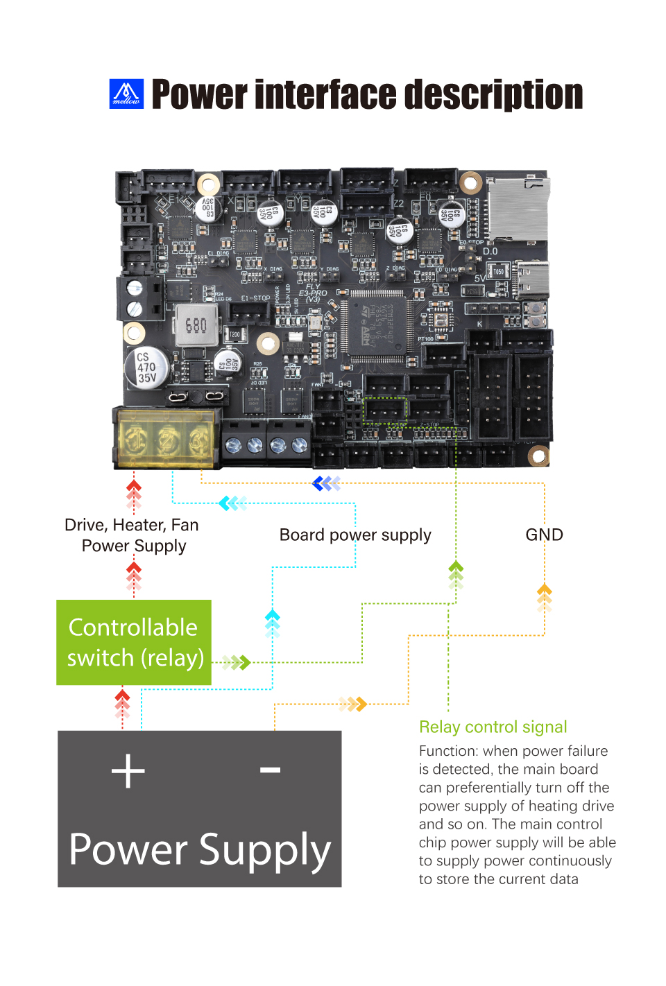
Power Configuration
The Fly-E3-Pro-v3 has two 24v inputs and one ground. The right 24v input powers the MCU and WiFi (as well as anything else that runs from 5v) and the left 24v input powers the motors, heaters and bed. This allows a relay to be used to turn off the motors, heaters and bed using a relay without having to use a separate 5v PSU to power the MCU. A diagragm can be found below.
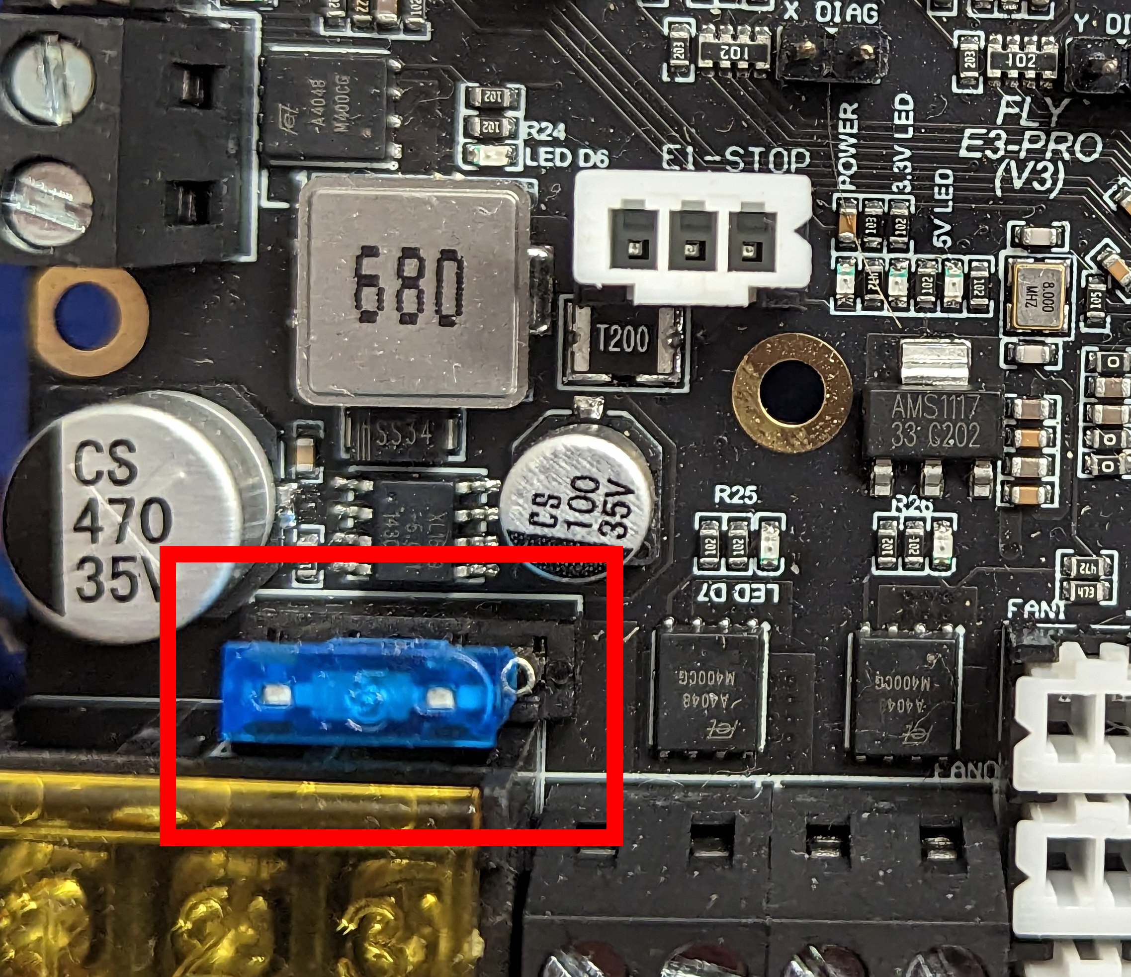
Fuse
Make sure you install the fuse as shown below.
Maximum Input voltage
The board can handle an input voltage up to 32v.
Thermistor inputs
The Fly-E3-Pro-v3 supports PT1000 on the thermistor inputs by using a 2k2 resistor rather than a 4k7. This is now pre-configured as part of the 3.5.0 release
Fan Mosfets
The Fly-E3-Pro-v3 has a unique feature in that the fan mosfets are replaceable. Each mosfet (VS3622e) controls two of the fan outputs. The orientation that the fan mostfet is plugged into the board doesn’t matter.
Initial Installation
The board that you will receive doesn’t have any firmware installed so when plugged into a computer, the board will show as an unidentified device. Follow the WiFi instructions.
Ender 3 Conversion
There is an Ender 3 Conversion guide that gives a full walkthrough from start to finish.