Overview
The Fysetc StrideMax Dual V2.0 can be connected to any of the Duet 3 range of mainboards produced by Duet3D, an STM32H723, STM32H743 or an STM32F4 with an spican module.
How to connect the board
CAN-FD only requires 2 wires to be connected between each board, CAN-H and CAN-L.
Connect the power cables to your 24/48v PSU.
The CAN-H connection on the Fysetc StrideMax Dual V2.0 should be connected to the CAN-H connection on the mainboard or spican module and the CAN-L connection on the Fysetc StrideMax Dual V2.0 should be connected to the CAN-L connection on the mainboard or spican module.
Commissioning
All boards in the system must have different CAN addresses. The Fysetc StrideMax Dual V2.0 are by default set to a CAN address of 124. Therefore, if you have more than one Fysetc StrideMax Dual V2.0 or an RP2040 based toolboard, only one of them must be powered up and connected to the CAN bus at a time until the CAN address has been changed. So disconnect power to all but one of them (you can leave the CAN bus connected if it’s easier).
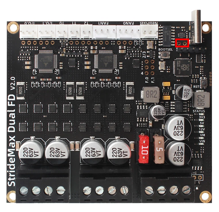
The Fysetc StrideMax Dual V2.0 supports both RRF CAN-FD and Klipper CAN 2.0. When setting up the board, you should ensure that the correct CAN mode is set by making sure there is no jumper fitted (for RRF mode) where highlighted below.
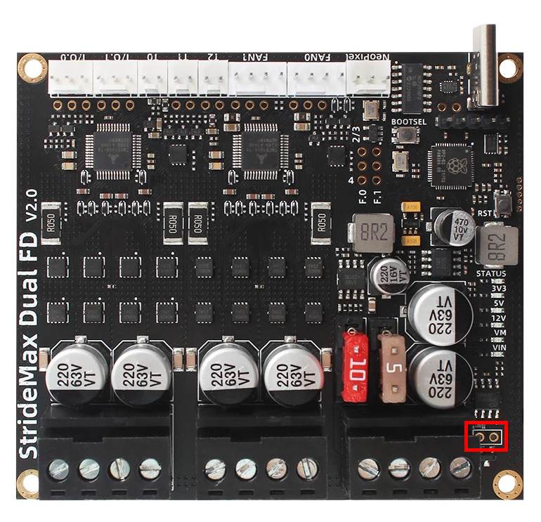
If the Fysetc StrideMax Dual V2.0 is the last board on the CANbus then it requires the 120ohm resistor enabling. To do so, install a jumper in the position shown below.
Checking the toolboard connection is functional
Power up the printer. All the Power LEDs on the Fysetc StrideMax Dual V2.0 should illuminate. You can then check that the toolboard is communicating correctly by sending the following command:
M115 B124
The firmware version running on the Fysetc StrideMax Dual V2.0 will then be reported.
Set the CAN address
- Send command M115 B# to verify that the main board can communicate with the Fysetc StrideMax Dual V2.0, where # is the original CAN address (normally 124)
- Send command M952 B# A## where ## is the new address you want to use. We suggest you use addresses starting at 30 for Expansion Boards. So for the first Fysetc StrideMax Dual V2.0, if your new CAN board was at address 124, send M952 B124 A30.
- Power the system down and up again, or send M999 B124. This will cause the Fysetc StrideMax Dual V2.0 to restart with the new address.
- Send command M115 B30 (or whatever address you chose) to verify that you can communicate with the Fysetc StrideMax Dual V2.0 at its new address
- You can now power up the next Fysetc StrideMax Dual V2.0 or Toolboard and commission it in the same way, choosing a different CAN address for it.
Startup Time
It is recommended to add the following to config.g, before any commands that reference any CAN bus connected expansion boards
G4 S2 ; wait for expansion boards to start