How to use the Fan headers on a StrideMax Dual V2.0
Overview
This page details how to use 2 wire, 3 wire and 4 wire fans with a StrideMax Dual V2.0.
Important: The StrideMax Dual V2.0 only supports 5V and 12V fans
Important: The changes shown below that are to be made to config.g assume that the StrideMax Dual V2.0 uses the default CAN address of 124. If you have changed the default CAN address, make sure you change the 124 to the correct address.
2 Wire Fans
To connect a 2 wire fan to the StrideMax Dual V2.0, you must ensure the following.
- Connect the black wire of the fan to the GND pin on the header.
- Connect the red wire of the fan to the +V pin on the header.
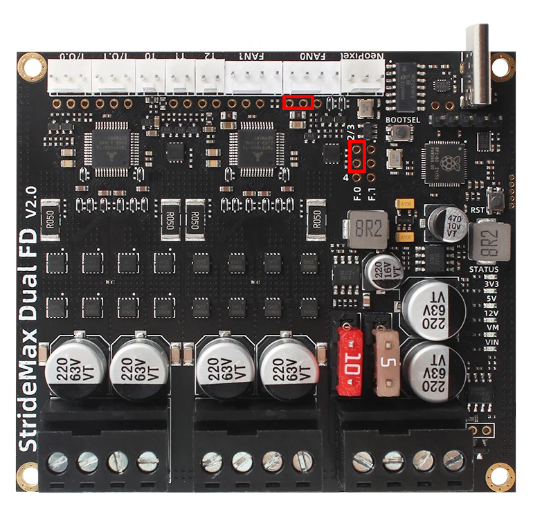
- Ensure the jumper beneath the connector is set to the correct voltage (5V or 12V).
- Ensure the jumper on the jumper on the F.0 or F.1 connector is connected to FAN_PWM pin and the middle pin.

Note: The image above shows Fan0 set as 12v
M950 F3 C"124.out0" Q100
M106 F3 S0 H-1
3 Wire Fans
To connect a 3 wire fan to the StrideMax Dual V2.0, you must ensure the following.
- Connect the black wire of the fan to the GND pin on the header.
- Connect the red wire of the fan to the +V pin on the header.
- Connect the blue wire of the fan to the tach pin on the header.
- Ensure the jumper beneath the connector is set to the correct voltage (5V or 12V).
- Ensure the jumper on the jumper on the F.0 or F.1 connector is connected to FAN_PWM pin and the middle pin.

Note: The image above shows Fan0 set as 12v
M950 F3 C"124.out0+tach0" Q100
M106 F3 S0 H-1
4 Wire Fans
To connect a 4 wire fan to the StrideMax Dual V2.0, you must ensure the following.
- Connect the black wire of the fan to the GND pin on the header.
- Connect the red wire of the fan to the +V pin on the header.
- Connect the blue wire of the fan to the tach pin on the header.
- Connect the yellow wire of the fan to the pwm pin on the header (next to the tach pin).
- Ensure the jumper beneath the connector is set to the correct voltage (5V or 12V).
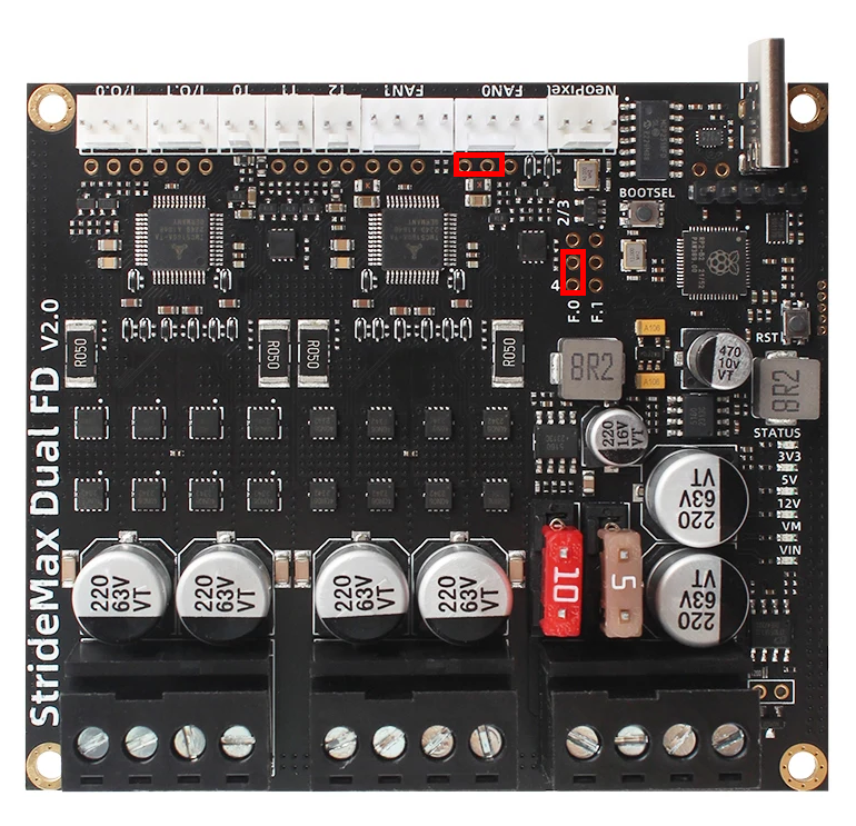
- Ensure the jumper on the jumper on the F.0 or F.1 connector is connected to 5V pin and the middle pin.

Note: The image above shows Fan0 set as 12v
M950 F3 C"!124.out0+tach0" Q100
M106 F3 S0 H-1