Overview
These instructions enhance the instructions provided by Formbot with the Troodon V2 Printer and are designed to be a replacement.
Tools
Most of the tools that are required to assemble the printer have been provided, however, the following tools will be required.
- Scissors
- 5.5mm Spanner/Adjustable Spanner/Pliers/5.5mm Socket
- Syringe with blunt tipped needle (size 16G and 18G needles required).
- Loctite
The following printable tools could assist with the assembly process
Pre-requisits
These instructions begin with the assumption that you have removed all the items from the box.
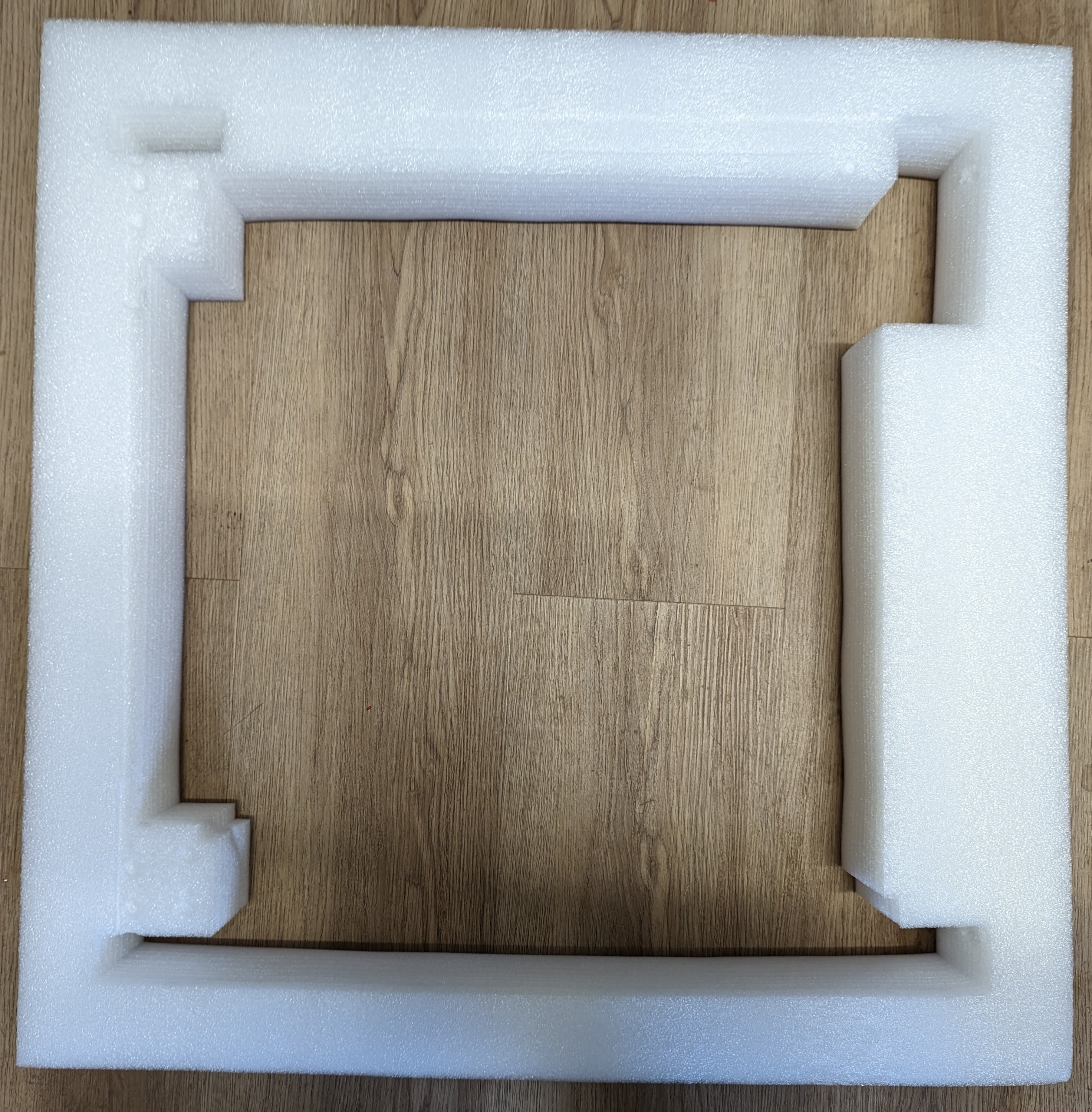
First, place this piece of packing foam on the surface you are going to build on.
Place the base upside down on this foam and remove the electronics bay cover.
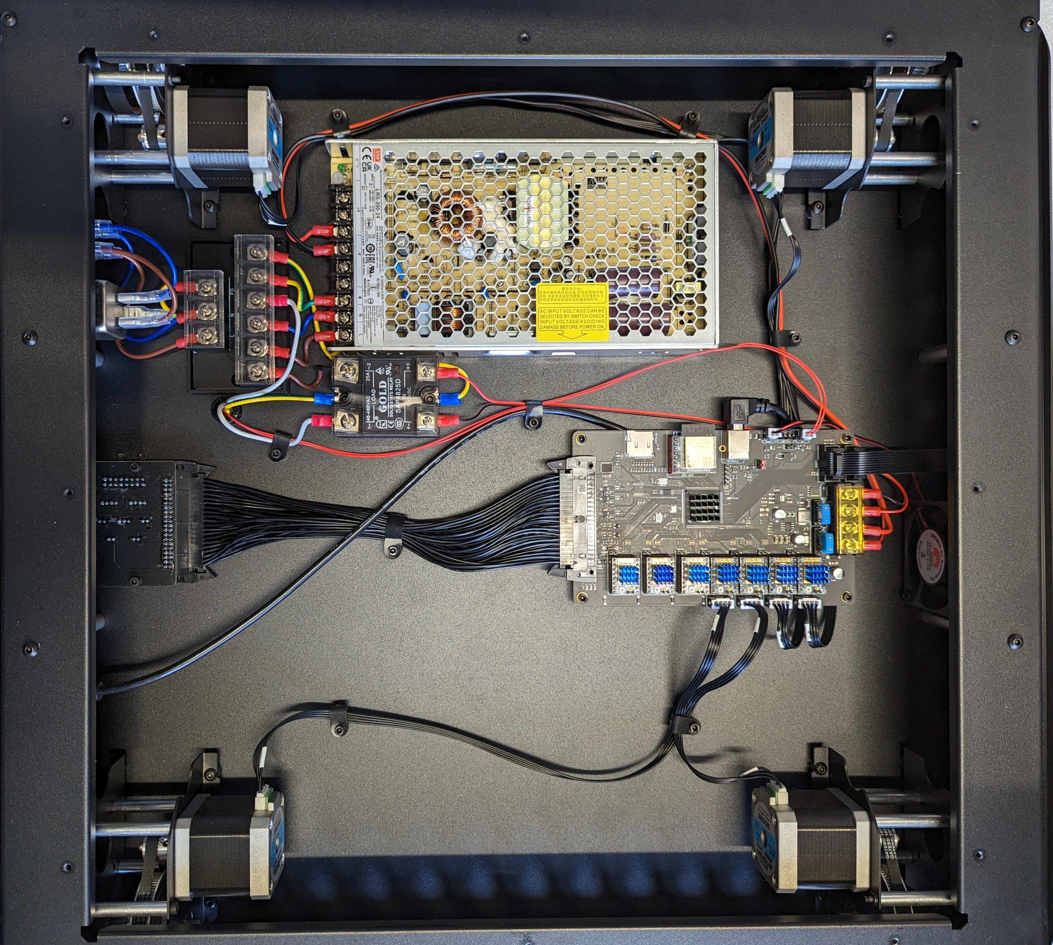
Check all the electrical connections are secure and nothing is loose.
Replace the electronics bay cover.
All of the linear rails supplied with the printer are not lubricated and therefore require lubrication.
Fill a syringe with the grease provided with the Troodon V2.
Use a 16G blunt tipped needle for the MGN9 Rails and an 18G blunt tipped needle for the MGN12 Rail.
Please see this video for further instruction.
Frame Assembly
Rather than just loosening the screws as instructed in the manual, using a 3mm allen key, remove each of the screws, apply loctite and reinstall them, with the suggested gap.
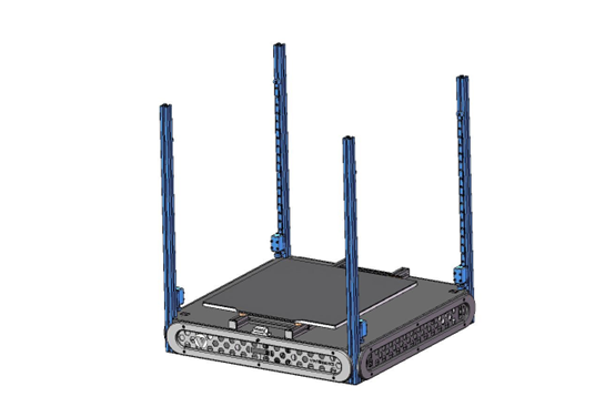
Install the Z extrusion as shown in the image below. Ensure the extrusions are flush against the metal sheet on the bottom of the printer. Tighten each of the screws until they are just gripping the extrusion to allow the extrusion to be pulled into position. Then fully tighten each screw.
Repeat for all for Z extrusions.
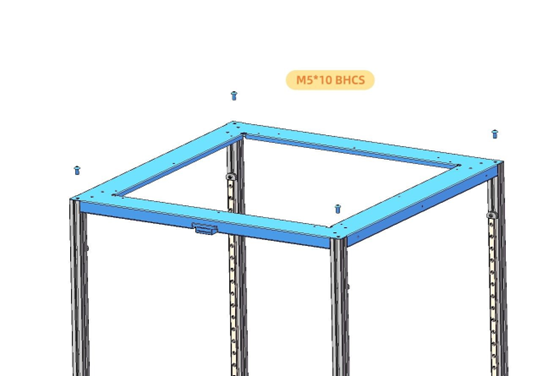
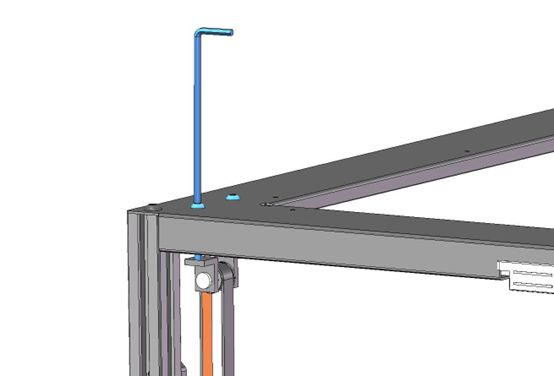
Mount the top plate to the printer, ensuring the LED is at the back of the printer and the door magnets are on the front. Use loctite on the screws when installing them.
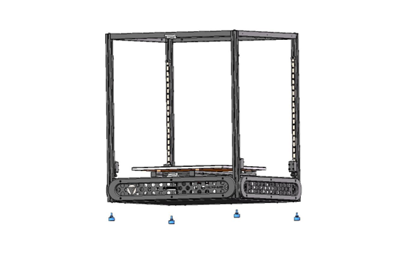
Install the feet to the bottom of the printer.
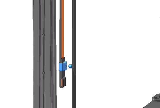
Loosely mount the idler pulleys. The screws should just protrude from the threaded hole in the brackets.
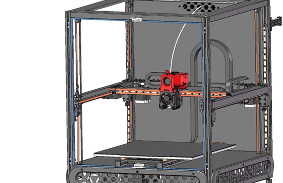
Inspect the toolhead and make sure all the cable ties are installed and the heat cables are not dangling below the nozzle.
Place a piece of foam onto the build platform.
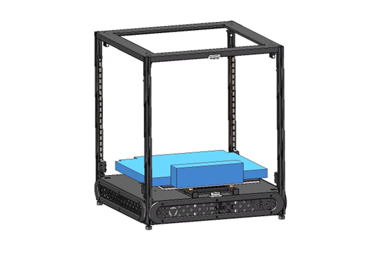
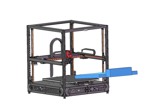
Lift in the gantry, at an angle, into the machine.
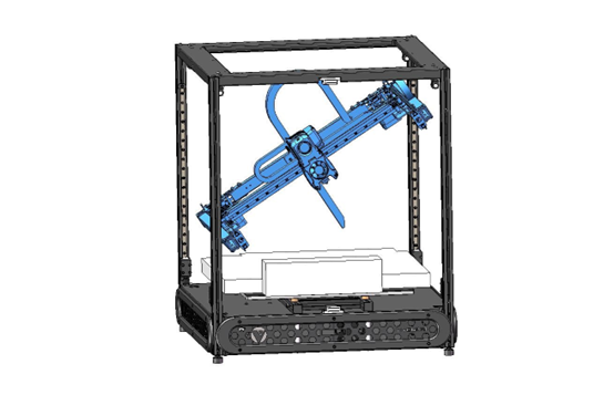
Place the gantry on the foam.
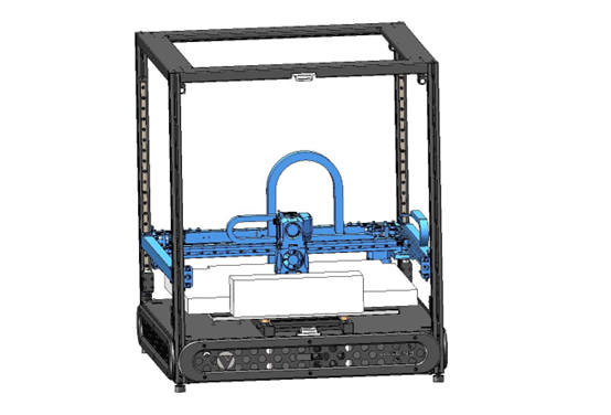
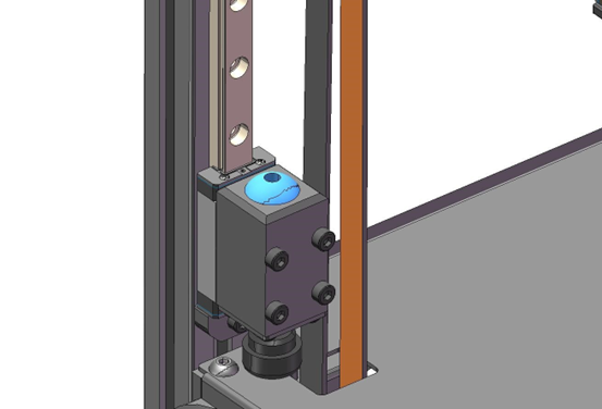
Hook the pre formed loop of the z belt on to the hook on the underside of the gantry.
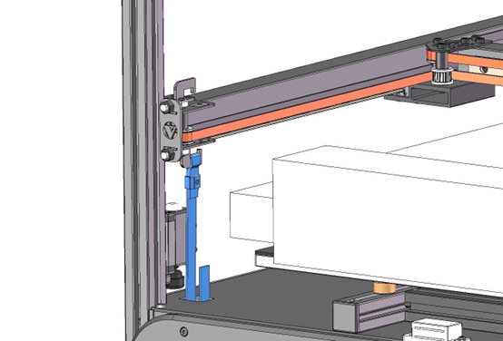
Pass the other end of belt through the sheet metals.
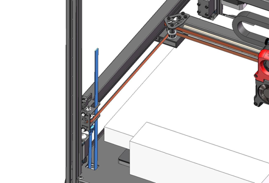
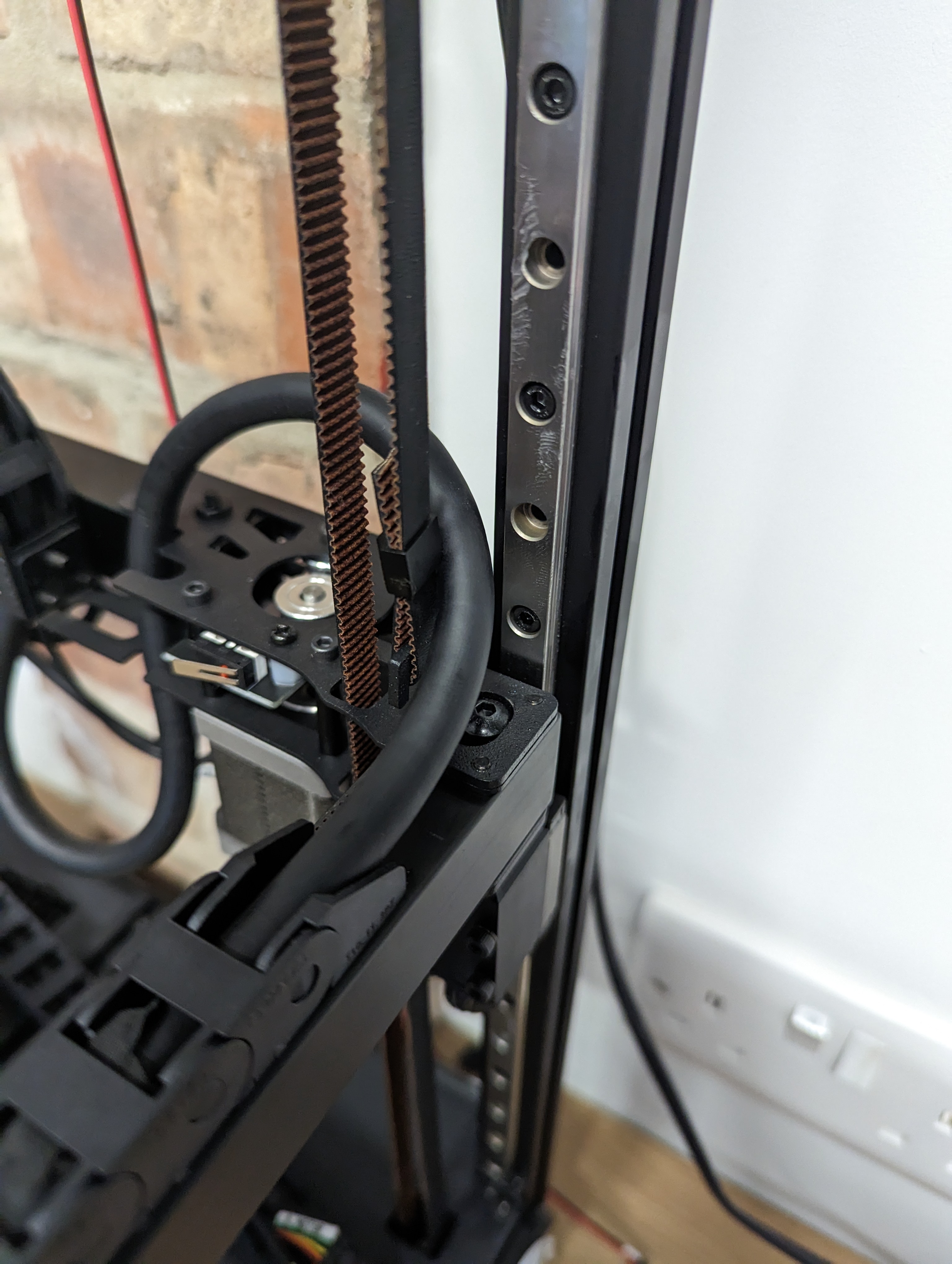
Pass belt through the top idler pulley.
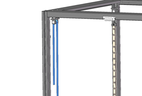
Install a buckle onto the belt with the treaded hole on the side with teeth.
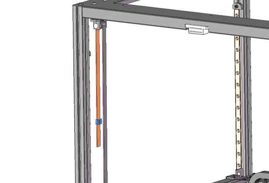
Pulling the belt taught, form a loop at the end of the belt. You want the loop to be positioned so it can just be hooked over the hook on the top of the gantry and doesn’t result in a belt that is too slack. Lifting the gantry slightly can aid in this process.
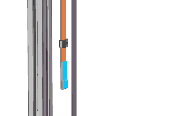
Slide the buckle over the looped up belt so it is about 15mm from the end. Apply loctite to the grub screw and install it using a 2mm allen key.
Hook the belt onto the hook on the top of the gantry.
Repeat for all 4 corners.
Rotate the screw holes of four movable hinges to the centre.
Install the M5x35 screw and spring washer. The screw should be aligned with the threaded hole of movable hinge. Fully tighten the screw. Install all four movable hinges in the same way.
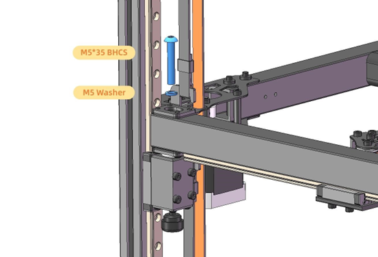
If it’s difficult to align the screws with the threaded holes on movable hinges, please loosen four M4 screws at the back of gantry for adjustment. Tighten back these M4 screws once all four holes are aligned.
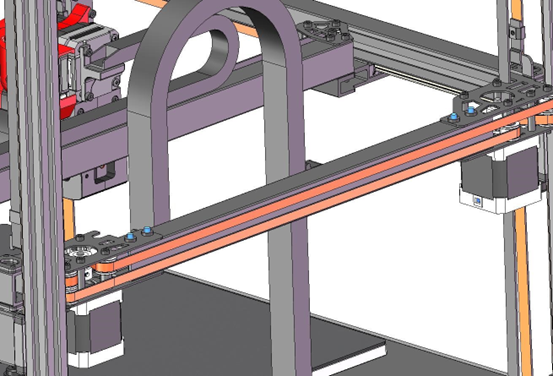
Now it is time to tighten the Z axis belts. Adjust the belts to 140Hz as described here
Remove the foam from on top of the build plate.
Plug the cables of drag chain into the breakout board according to labels on each cable and the yellow label on the prtiner base.
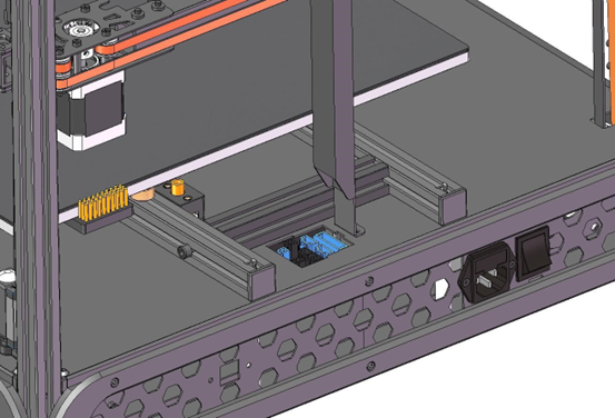
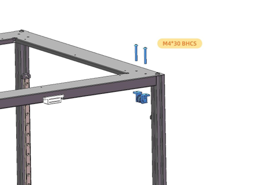
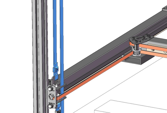
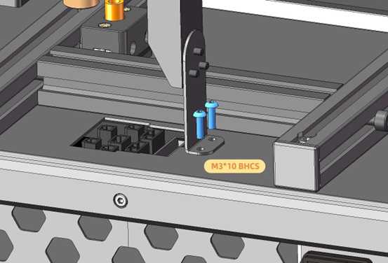
Install the Z axis drag chain bracket.
Panel Assembly
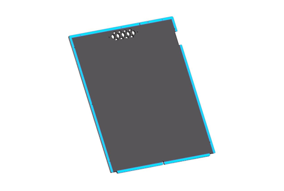
Remove the protective film from both sides of the rear black panel.
Attach 1mm foam tape onto the inner side of the black back panel as shown.
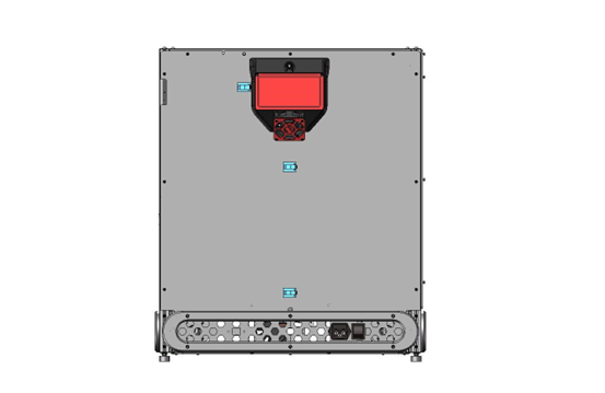
Attach VHB tape to the air filter as shown.
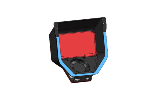
Install the activated carbon filter into the air filter.
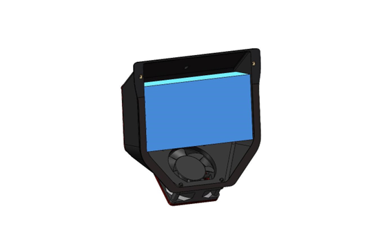
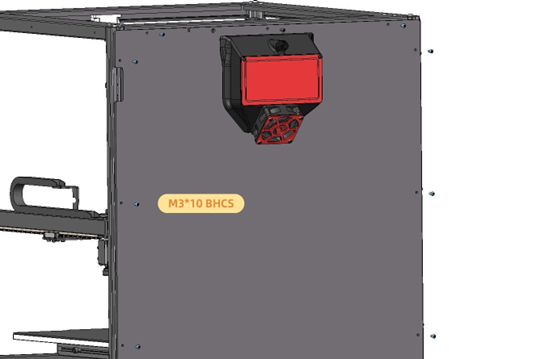
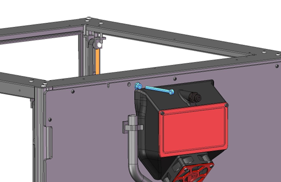
Attach the air filter to the outside of the black back panel.
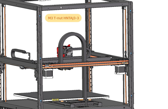
Install 6pcs M3 T-nuts in the positions shown below.
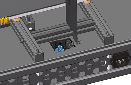
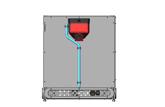
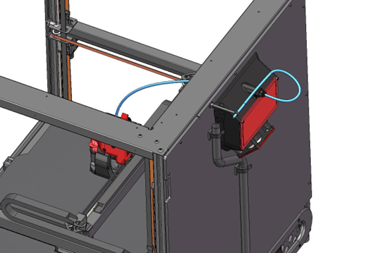
Plug the cables for the air filter, LED light and filament runout sensor into the breakout board as shown. Use the yellow label on the base for guidance.
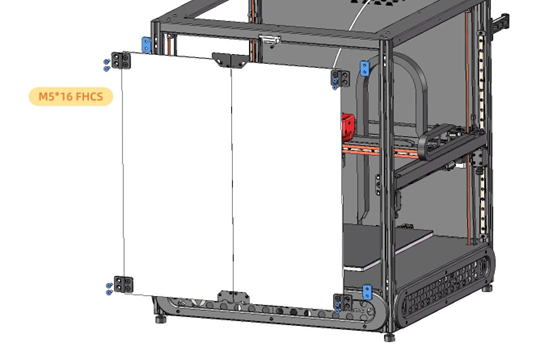
Install the back panel into the slot on the skirt, guiding the 3 cables through the slot in the bottom of the back panel.
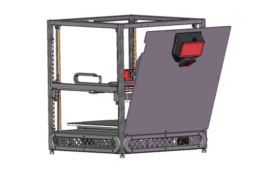
Push the back panel against the frame and pass the LED light cable through the slot at the top.
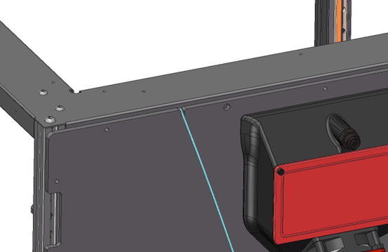
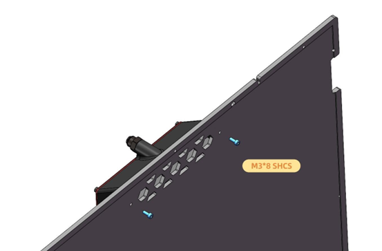
Attach the back panel to the frame using 9 x M3x10mm screws.
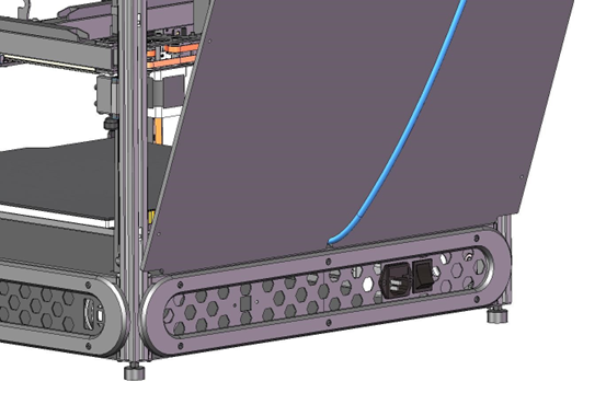
Attach the 3 cable ties to the back panel as shown below.
Wrap the 3 cables in the included cable braid.
Secure the cables in the 3 cable ties.
Install the screw bracket for PTFE tube.
Move the extruder to the front left corner, close to the bed, and install the PTFE tube. (Note: please reserve enough length of PTFE tube inside chamber, or else, the extruder will be pulled up during print)
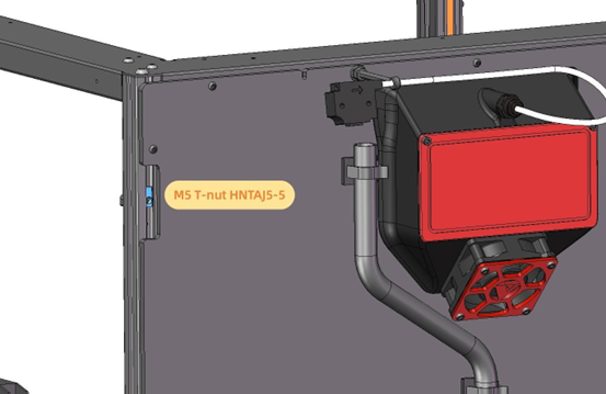
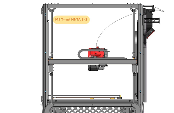
Install an M5 T-nut in the positions shown below.
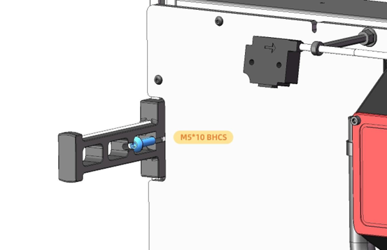
Install the filament spool holder as shown below.
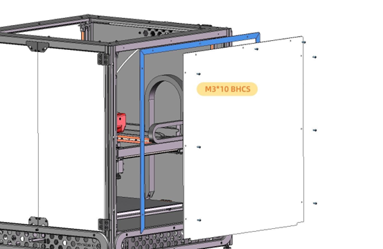
Remove the protective film from both sides of the door panels.
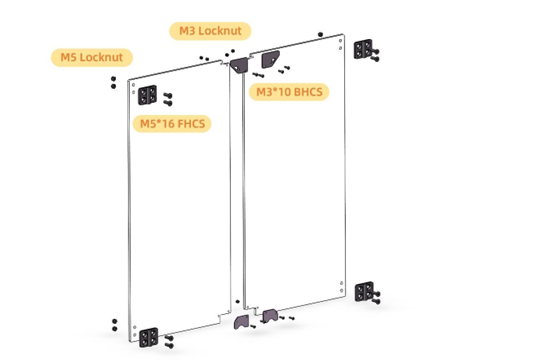
Install the hinges and metal brackets to the door panels as shown below. The supplied spanner works for the M5 locknuts but a 5.5mm Spanner/Adjustable Spanner/Pliers/5.5mm Socket will be required for the M3 locknuts. Ensure the hinges are square to the panels when tightening the screws.
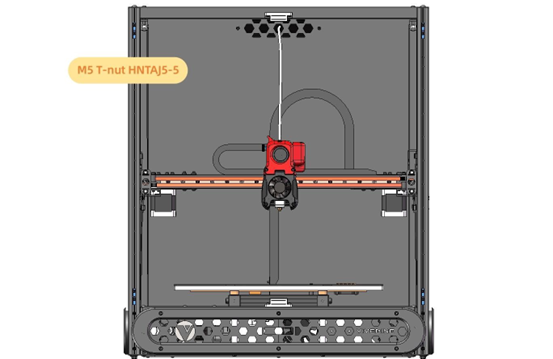
Install 8pcs M5 T-nuts in the positions shown below.
Attach 3mm foam tape to the frame for sealing as shown below.
Remove the protective film from both sides of the hinge spacers.
Attach the front doors onto frame by screws. Make sure you install the hinge spacers between the frame and the hinges. Before fully tightening the sncrews for the hinges, test that the doors are equally spaced vertically and can be easily open and closed.
Remove the protective film from one of the side panels.
Attach 3mm foam tape to the side panel as shown.
Install 6pcs M3 T-nuts in the positions shown below.
Remove the protective film from both sides of 3 of the side panel spacers.
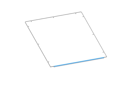
Attach the side panel onto frame as shown below. Ensure the foam strip on the bottom of the side panel faces into the machine.
Repeat the steps above for the other side panel.
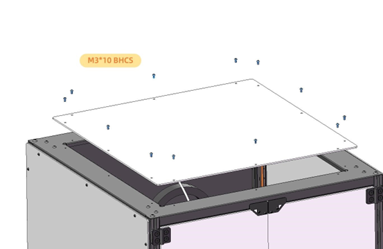
Remove the protective film from both sides of the top panel.
Attach 3mm foam tape around the outside edge one side.
Install the top panel to the frame.
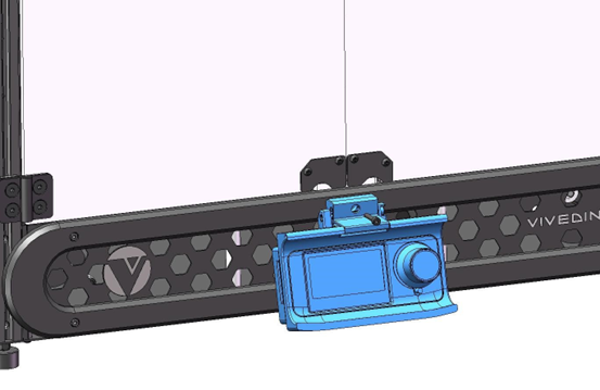
Remove the screw in the position shown below.
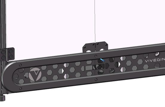
Connect the two ribbon cables according to the label behind screen, then mount the screen using the screw.
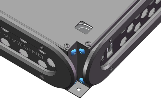
Install the four corner guards.
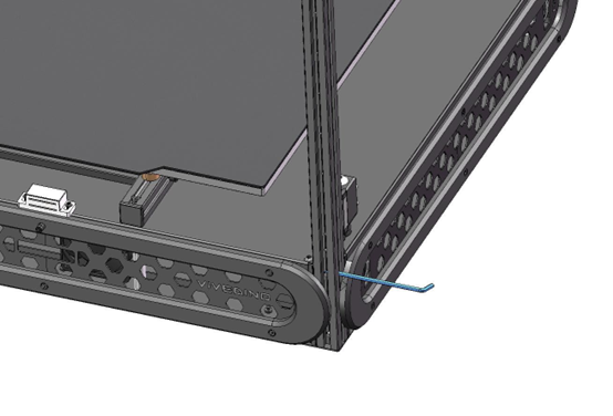
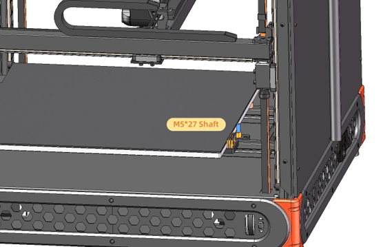
Install the shaft into autoZ probe.
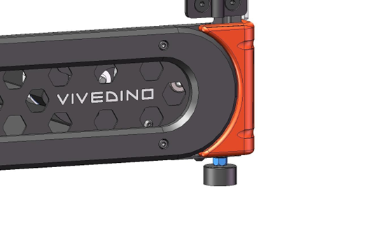
Rotate four foot pads to level the machine and lock the foot pads by the nuts as shown below.
Remove the flexible build platform and remove the protective film from the smooth side.