Overview
The Fly-CDY is an LPC1769 based board.
This board is very unique in that it has been created as a reprapfirmware board first and foremost.
That means than unlike other LPC based board, an ESP8266 has been provided on board, no adapter required.
Board Preparation
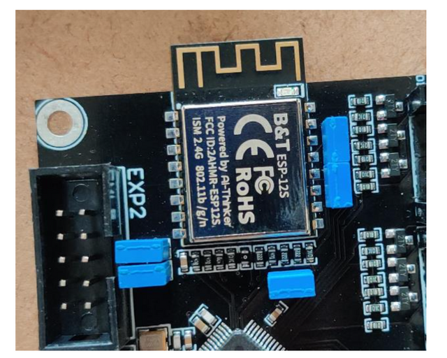
Certain jumpers are required to be fitted to the board before the onboard wifi module can be used.
Make sure your jumper arrangement matches the following image.
Flashing the board firmware
Choose the correct corresponding firmware (firmware-lpc-wifi-XXX.bin) from here. Remember to rename it to firmware.bin. Put it in the root of a FAT32 formatted SD card.
WiFi firmware preparation
Choose the correct corresponding firmware (DuetWiFiServer-esp8266-lpc.bin) from here. Remember to rename it to DuetWiFiServer.bin. Put it in a folder called firmware in the SD card.
Prepare the SD Card
Follow the instructions on Getting Started with RRF3
Board.txt file
You will also need a board.txt file in the sys folder. Below are the contents that should be used.
//Config for fly-CDY
board = fly_cdy
//WiFi pins
8266wifi.espDataReadyPin = 0.28;
8266wifi.TfrReadyPin = 2.7;
8266wifi.espResetPin = 2.6;
8266wifi.serialRxTxPins = { 0.1, 0.0 } ;
heat.tempSensePins = { 0.23, 0.26, 0.25 }
Smart Drivers
If using TMC22XX drivers (thats either the TMC2208, TMC2209, TMC2225 or TMC2226), the following line must also be added to the board.txt file
stepper.numSmartDrivers = X
Where X is the number of drivers fitted. The drivers must be continuous and start at unit 0. So, for the SKR board, if you have say 3 TMC2208s and 1 other driver, the 2208s must be in slots 0, 1, 2 and the remaining driver in slot 3 or 4. You can use RRF to assign any of those slots to an axis/extruder.
Sensorless Homing
If using sensorless homing/stall detection (supported by only the TMC2209 or TMC2226), the following line must be added to the board.txt file.
stepper.TmcDiagPins = {1.29, 1.28, 1.27, 1.25, 1.22, 1.19}
Please only include the diag pin numbers where you intend to use sensorless homing on that axis. For example, if you only intend to use sensorless homing/stall detection on driver 0 and driver 1, only include 1.29 and 1.28 in your board.txt file.
For more information about setting up sensorless homing, please read this.
Driver Diag Pin
The driver diag pin is used for sensorless homing and stall detection.
The Fly-E3 does not have a way of disabling the diag pin as it is designed to be used with Fly-2209 drivers which have a switch on the underside of them for disabling the diag pin.
If you plan on using endstops rather than sensorless homing and do not have the Fly-2209 drivers, you need to bend or remove the diag pin.
Board.txt Location
Place the board.txt file in a directory called “sys” on the SD card and install the SD card in the Fly-CDY.
Config.g adjustments
The fly-CDY board is delivered without any firmware on the WiFI chip so as part of that process we need to set it up.
Open the config.g file that has been placed in the sys folder of the SD card and comment out any M552 commands that are there using ; e.g. ;M552 S1.
Final Setup
Once connected, power up the board using 12-24v and connect to the USB port on the board. Using a program such as putty. Follow the instructions here to set it up for RRF. Then type in the following
M997 S1
Wait for the uploading of the WiFi firmware to finish. Then send the following
M552 S-1
M552 S0
M587 S"your SSID" P"your password"
M552 S1
If you wanted to use “PassWord”, you would write P”P’a’s’sW’o’r’d” with the ‘ indicating the following letter should be lower case. Explanation here.
The blue light on the WiFi chip shoould then flash blue and will go solid when a connection has been established. The ip address will be shown on the serial connection. It is also possible to type just M552 to get the current ip address reported back.
The final thing to do is add the line “M552 S1” to your config file. This can be done through the web interface. This just ensures that the WiFI connection is started at start up. There is no need to add the M587 command as this is written permanently to the flash of the ESP8266 chip.
Once up and running
You will need to PID tune your tools and your bed. Please be aware that bed tuning may take up to an hour and tool tuning normally takes around 15 minutes. If it takes longer, that is also fine as up to 30 cycles may be ran.
To tune the bed, run the following command, changing the temperature (the S value) if a different tuning temperature is required.
M303 H0 S60
To tune each tool, run the following command, changing the temperature (the S value) if a different tuning temperature is required. This proceedure will activate the part cooling fans during the final phase of the tuning process so their effect is taken into account. If your printer has more than one tool, make sure each one of them is tuned.
M303 T0 S220
Once the tuning is complete, either copy the M307 command into the heater definitions or send M500, ensuring you have M501 at the end of your config.g.
If the tuning fails at the end, carry on saving the values as in most cases the outputted values still work correctly.
If the values still result in a heater fault, please refer to this wiki page for information about how to adjust the values manually.