Overview
The BTT Kraken is an STM32H723VGT6 based board.
Since RRF 3.5-RC4, firmware for STM32F4, STM32H723 and STM32H743 boards works as follows:
- Each board has its own firmware file, instead of one firmware file covering many boards.
- WiFi mode and SBC mode are both included in the same firmware file. If an SD card is present, the board starts in WiFi mode. If no SD card is present, the board starts in SBC mode. This is the same way that Duet3D boards work.
- A board.txt setting selects which type of WiFi module is installed.
Downloading the board firmware
TeamGloomy provides a separate firmware file for each board. The correct file for this board is firmware_kraken_h723.bin.
The latest firmware files can be found here
You can download either the latest stable release or the latest pre-release, if one is available.
Once downloaded, rename the file to firmware.bin.
WiFi firmware preparation
The latest firmware files can be found here
- WiFiModule_esp32.bin
DWC (DuetWebControl)
The correct version of DWC should be downloaded from here.
The version you download should be of the same version number as the board firmware you downloaded above.
For example, if version 3.5.0 of the board firmware has been downloaded, 3.5.0 of DWC should be downloaded.
Purchasing the WiFi Adapter
You will need a WiFi adapter that plugs into the EXP2 header. It can be purchased here:
- Mellow (who works in close collaboration with TeamGloomy) on Aliexpress
Connecting the WiFi Adapter
Connect the ESP32 adapter to the board as shown below. You also need to connect the antenna.
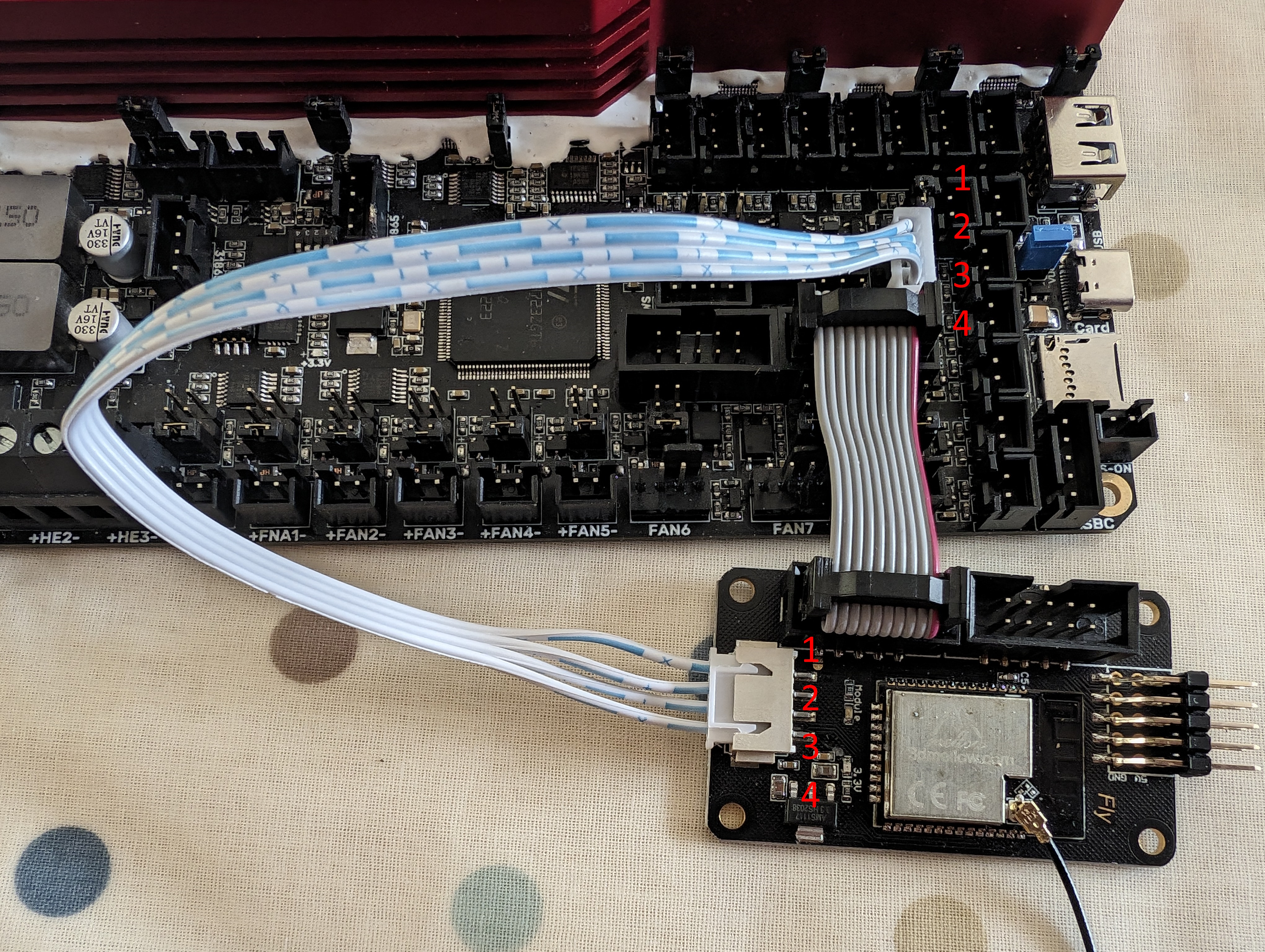
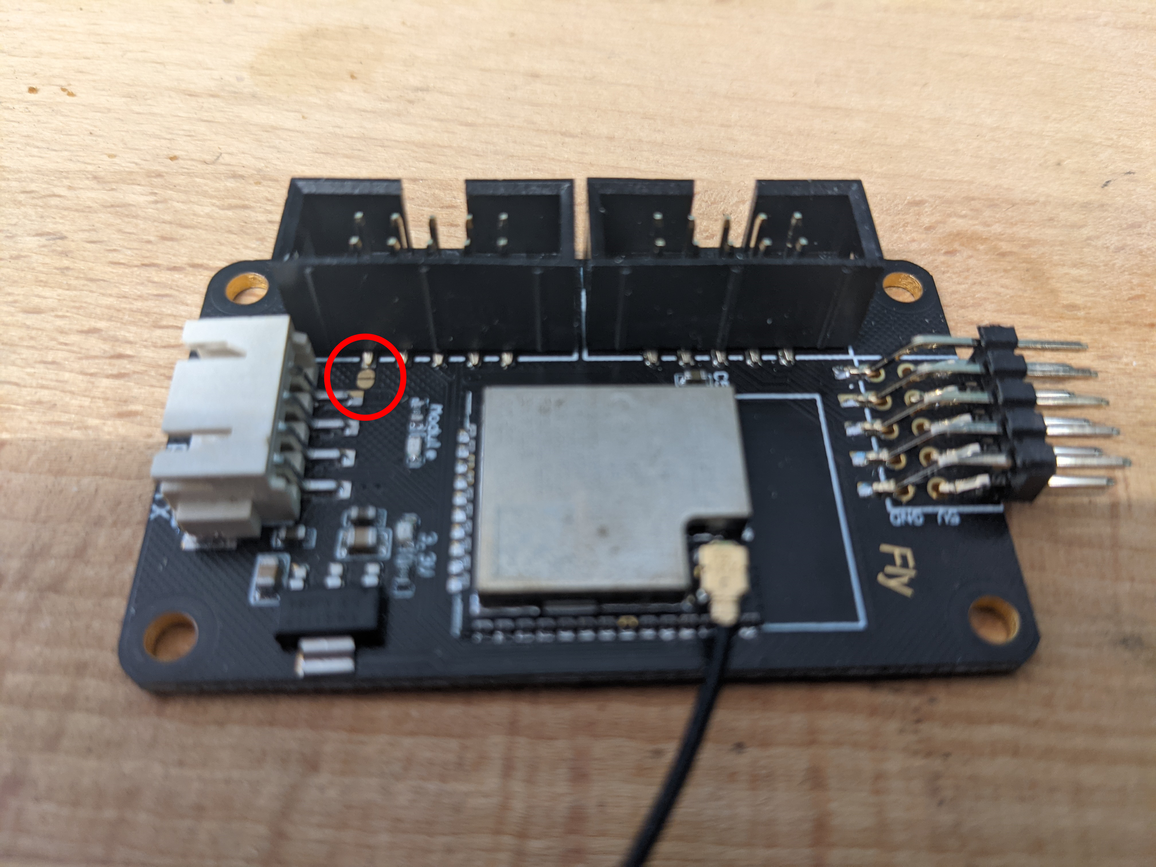
If you do not need to update the WiFi adapter firmware from the BTT Kraken, you do not need to connect the 4-pin serial cable. Instead, add a small amount of solder in the area highlighted below to get power from EXP2.
Generate a config
We provide a handy online tool to help you generate a set of config files for your 3D printer. The configurator does not cover every RRF option (for example, dual motor axis control, which can be added manually later), but it gives you a good starting point.
We also have a collection of user created configs which can be a useful reference. They can be found here
Manual board.txt Changes
If you are using a set of config files provided by someone else, or do not need to use the configurator, you may need to create your board.txt file manually. Most board.txt settings are already pre-configured for each board. The preset settings for the BTT Kraken are listed below for reference.
board=kraken_h723
board.longName="BTT Kraken V1 STM32H723"
sdcard.internal.type=5
SPI0.pins={NoPin,NoPin,NoPin}
SPI1.pins={B.13,B.14,B.15}
SPI2.pins={C.10,C.11,C.12}
SPI3.pins={C.6,C.7,C.8}
SPI4.pins={NoPin,NoPin,NoPin}
SPI5.pins={D.13,D.15,D.12}
SPI6.pins={E.12,E.13,E.14}
SPI7.pins={NoPin,NoPin,NoPin}
SPI8.pins={NoPin,NoPin,NoPin}
stepper.powerEnablePin=NoPin
stepper.enablePins={E.6,E.3,E.0,B.7,G.13,G.12,B.5,G.14}
stepper.stepPins={C.14,E.5,E.2,B.9,G.9,G.11,B.4,G.15}
stepper.directionPins={C.13,E.4,E.1,B.8,G.10,D.7,B.3,B.6}
stepper.numSmartDrivers=8
stepper.num5160Drivers=8
stepper.spiChannel=3
stepper.TmcUartPins={D.6,D.5,D.4,D.3,D.2,A.15,A.9,A.10}
power.VInDetectPin=NoPin
sbc.TfrReadyPin=G.6
sbc.csPin=E.11
sbc.spiChannel=6
wifi.espDataReadyPin=G.8
wifi.TfrReadyPin=G.7
wifi.espResetPin=G.6
wifi.spiChannel=6
wifi.csPin=E.11
wifi.serialRxTxPins={D.9, D.8}
wifi.serialRxTxPins={B.11,B.10}
wifi.moduleType=esp32
heat.tempSensePins={B.0,B.1,C.5,C.4,A.7}
can.writePin=D.1
can.readPin=D.0
serial.aux.rxTxPins={D.9,D.8}
heat.spiTempSensorChannel=2
heat.spiTempSensorCSPins={C.9,A.8}
Unless you are overriding some of the above settings, or adding additional features, such as an accelerometer or 12864 display, a board.txt file is not required.
Sensorless Homing
Follow the instructions as found here
You can now continue getting the SD card in the correct format.
SD Card preparation
Now all the required files have been gathered, the SD card structure needs to be created.
SD Card Specification
When choosing an SD Card to use with RRF, we recommend one with the following features:
- a branded card with a speed rating of Class 4 or higher
- of up to 32GB capacity, formatted as below. RepRapFirmware does not support SD cards formatted in exFAT format.
Formatting
If you can’t use the recommended formatting tool, note the following when formatting the micro SDHC card:
- If the capacity of the card is 4GB or lower, use FAT16 format
- If the capacity is more than 4GB (up to 32GB) then you will have to use FAT32 format
- All cards should be formatted with 512 byte sectors
- For best upload speed choose the largest cluster size available, which is normally 64kb for FAT16 and 32kb for FAT32
SD Card Structure
The following structure should be replicated on your SD card.
sd card root/
├─ filaments/
├─ firmware/
│  ├─ WiFiModule_esp*.bin
├─ gcodes/
├─ macros/
├─ sys/
│  ├─ bed.g
│  ├─ board.txt (if required)
│  ├─ config.g
│  ├─ homeall.g
│  ├─ homex.g
│  ├─ homey.g
│  ├─ homez.g
│  ├─ pause.g
│  ├─ resume.g
│  ├─ sleep.g
│  ├─ stop.g
│  ├─ tfree0.g
│  ├─ tpost0.g
│  ├─ tpre0.g
├─ www/
│  ├─ contents of DuetWebControl-SD.zip
firmware.bin
In the above example, the contents of the sys folder have come from the online configurator. The WiFiModule file name will either be:
- WiFiModule_esp32.bin
- WiFiModule_esp32eth.bin
Final Setup
Once connected, power up the board using 12-24V and connect the USB port on the board to your computer. Connect to the board using a program such as PuTTY. Follow the instructions here to set it up for RRF. Change the COM port to match the BTT Kraken and connect. The baud rate does not matter.
Flashing the WiFi Firmware
Type in the following to putty
M552 S0
M997 S1
Wait for the uploading of the WiFi firmware to finish.
Sending your WiFi Credentials
Send the following
M552 S0
M587 S"your SSID" P"your password"
M552 S1
If you wanted to use
PassWord, you would write P"P'a's'sW'o'r'd", with the ' indicating that the following letter should be lower case. Explanation here.The blue light on the WiFi module should flash, then turn solid once a connection is established. The IP address is shown on the serial connection. You can also type M552 on its own to see the current IP address.
The final step is to add the line M552 S1 to your config.g file. You can edit config.g through the web interface. This makes sure that WiFi starts automatically when the board powers on. You do not need to add the M587 command to config.g, since it is saved permanently to the WiFi module.
Once up and running
You will need to PID tune your tools and your bed. Bed tuning may take up to an hour, and tool tuning normally takes around 15 minutes. If it takes longer, that is fine — up to 30 tuning cycles may run.
To tune the bed, run the following command, changing the temperature (the S value) if a different tuning temperature is required.
M303 H0 S60
To tune each tool, run the following command, changing the temperature (the S value) if a different tuning temperature is required. This process turns on the part cooling fans during the final phase of tuning, so their cooling effect is accounted for. If your printer has more than one tool, make sure each tool is tuned.
M303 T0 S220
Once the tuning is complete, either copy the M307 command into the heater definitions or send M500, ensuring you have M501 at the end of your config.g.
If the tuning fails at the end, carry on saving the values as in most cases the outputted values still work correctly.
If the values still result in a heater fault, please refer to this wiki page for information about how to adjust the values manually.